This thread has been locked.

If you have a related question, please click the "Ask a related question" button in the top right corner. The newly created question will be automatically linked to this question.

DLPC3430:About DLPC3430+DLP2010+DLPA2000 after lighting up, there will be a snowflake screen problem after staying on.

Part Number: DLPC3430
Other Parts Discussed in Thread: DLPA2000, , DLP2010

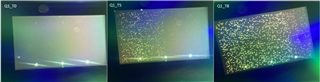
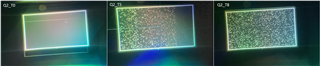
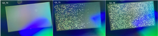
Dear TI engineer, hello! We are working on lighting DLP2010+DLPC3430+DLPA2000. The equipment is currently lit and the pictures are drawn normally, but after we put the machine for a period of time, dots of pictures will appear. We use fans to dissipate heat. Disappeared, we don’t know if it is caused by heat or my DSI is configured incorrectly. Do you have a similar case that can be solved?

  • Hello Jianwei,

    Welcome to DLP forum and thank you for your interest in DLP technology.

    I want to reconfirm your system configuration:

    You are using DSI interface to transfer the data to projection module.  What is front-end processor i.e driving the DSI line? 

    Could you please also share details about video requirement (frame rate, Pixel etc) and DSI configuration of controller.

    Problem observed -  After the system runs for some time, you notice image artifacts. This problem disappears if you cool the board with fan.

    If above is correct, very likely you are violating the DSI constraints of the DLPC3430 controller. Please review to DLPC3430 datasheet for DSI and also DSI debug guide 

    https://e2e.ti.com/support/dlp-products-group/dlp/f/dlp-products-forum/846660/faq-dsi-setup-and-debugging-guide

    https://www.ti.com/lit/ds/symlink/dlpc3430.pdf

    Please review the the DSI configuration setting listed in page 5 of the debug guide. We have observed that system one work fine with one or two violation of some of the required setting. It start have artifact as system warms.

    regards,

    Vivek

  • Thanks a lot for your reply.

    We use Qualcomm sm6115 SOC as the output of DSI. I will share the specific DSI configuration with you. It is included in the attachment. As you said, after the system runs for a period of time, it starts to appear and disappears after cooling with a fan. We will continue to check the related problems through the link you gave us.

  • Qualcomm Linux kernel dtsi configuration

    dsi-panel-wo-dlp-wvga-video.zip

  • Hello Jianwei,

    I am not able to open Qualcomm configuration file. Could you please share in text or excel format?

    One feedback - You are operating at DSI HS clock ate 84 MHz Please try to increase the clock frequency by increasing the blanking. The minimum supported DSI HS clock is 80MHz and it is good practice to operate from away from the min and  max limit. This will provide much needed margin for such thermal issue if HS clock is root cause for this problem.

    regards,

    Vivek

  • Thank you very much for your reply. We tried to increase the clock frequency from 86MHZ to 98MHZ. The problem still exists. We used the same machine to test under the same brightness, room temperature and black picture. About three minutes later, the screen started to appear. Very slight red dots. At about 5 minutes, the screen started to be mixed with white dots and red dots. At this time, the phenomenon was obvious. At about 8 minutes, the screen began to appear large areas of white dots, almost full The entire screen. 86MHZ and 98MHZ phenomenon are the same, so I feel that increasing the frequency has no effect, and when I am in the pattern mode, that is, the control register 0x0B, this situation will also occur. The time when the light spot appears is almost the same as the situation with DSI.

    dsi-panel-wo-kernel-dtsi.txt
    &mdss_mdp {
    	dsi_wo_dlp_wvga_video: qcom,mdss_dsi_wo_dlp_wvga_video {
    		qcom,mdss-dsi-panel-name = "Wo dlp wvga video mode dsi panel";
    		qcom,mdss-dsi-panel-type = "dsi_video_mode";
    
    		qcom,dsi-ctrl-num = <0>;
    		qcom,dsi-phy-num = <0>;
    
    		qcom,mdss-dsi-virtual-channel-id = <0>;
    		qcom,mdss-dsi-stream = <0>;
    
    		qcom,mdss-dsi-bpp = <24>;
    		qcom,mdss-dsi-underflow-color = <0xff>;
    		qcom,mdss-dsi-border-color = <0>;
    
    		qcom,mdss-dsi-traffic-mode = "non_burst_sync_event";
    		qcom,mdss-dsi-bllp-eof-power-mode;
    		qcom,mdss-dsi-bllp-power-mode;
    		qcom,mdss-dsi-force-clock-lane-hs;
    		qcom,mdss-dsi-tx-eot-append;
    		qcom,mdss-dsi-lane-0-state;
    		qcom,mdss-dsi-lane-1-state;
    		qcom,mdss-dsi-lane-2-state;
    		qcom,mdss-dsi-lane-3-state;
    
    		qcom,mdss-dsi-dma-trigger = "trigger_sw";
    		qcom,mdss-dsi-mdp-trigger = "none";
    		qcom,mdss-dsi-bl-pmic-control-type = "none";
    		qcom,mdss-dsi-reset-sequence = <1 10>, <0 10>, <1 10>;
    
    		qcom,mdss-dsi-display-timings {
    			timing@0 {
    				qcom,mdss-dsi-panel-width = <854>;
    				qcom,mdss-dsi-panel-height = <480>;
    
    				qcom,mdss-dsi-h-front-porch = <38>;
    				qcom,mdss-dsi-h-back-porch = <24>;
    				qcom,mdss-dsi-h-pulse-width = <24>;
    				qcom,mdss-dsi-h-sync-skew = <0>;
    
    				qcom,mdss-dsi-v-back-porch = <14>;
    				qcom,mdss-dsi-v-front-porch = <8>;
    				qcom,mdss-dsi-v-pulse-width = <7>;
    
    				qcom,mdss-dsi-h-left-border = <0>;
    				qcom,mdss-dsi-h-right-border = <0>;
    
    				qcom,mdss-dsi-v-top-border = <0>;
    				qcom,mdss-dsi-v-bottom-border = <0>;
    
    				qcom,mdss-dsi-h-sync-pulse = <0>;
    				qcom,mdss-dsi-panel-framerate = <60>;
    
    				//qcom,mdss-dsi-on-command = [];
    				//qcom,mdss-dsi-off-command = [];
    				//qcom,mdss-dsi-on-command-state = "dsi_lp_mode";
    				//qcom,mdss-dsi-off-command-state = "dsi_hs_mode";
    			};
    		};
    	};
    };
    

    Here we share some test result and analysis . 

    Precondition:

    1. Keep the display off and cool it to the room temperature. 
    2. Keep testing the same device.
    3. Show black in the display.
    4. Keep the same brightness in all the tests with RGB LED to 200.


    Q1: If we increase the DSI clock, can the bright dot issue be observed as well?

    A1: We tried to set it to 98MHz and the bright dot is observed.


    Steps: Set different DSI clock.


    After 3min

    After 5min

    After 8min

    86MHz

    Weak  red dots are observed.

    Obvious  white and red dots are observed, but not all over the display area. They are  mainly on the left side.(Q1_T5)

    The  white dots are all over the area.(Q1_T8)

    98MHz

    Weak  red dots are observed.

    Obvious  white and red dots are observed, but not all over the display area. They are  mainly on the left side.(Q1_T5)

    The  white dots are all over the area.(Q1_T8)


    Q2: Turn off DSI output, set the register 0x0BWrite Test Pattern SelectW 0xD7 0x01)W 0x05 0x01(W 0x0B 0x80 0x00 ). No image input and it only shows the black pattern.

    A2: The bright dot is observed after 8 mins.


    After  3min

    After 5min(Q2_T5)

    After 8min(Q2_T8)

    Weak red dots are observed.

    Obvious  white and red dots are observed, but not all over the display area. They are  mainly on the left side.

    The  white dots are all over the area.


    Q3: Turn off DSI output. Set the display to DisplayImageCurtain mode (W 36 16 01.

    A3: The bright dot is observed after 8 mins.


    After  3min

    After 5min(Q3_T5)

    After 8min(Q3_T8)

    Weak red dots are observed.

    Obvious  white and red dots are observed, but not all over the display area. They are  mainly on the left side.

    The  white dots are all over the area.


    Based on the result above, we know that the bright dots are observed even without DSI signal. The time when it is observed is the same with or without the DSI signal. 

    The bright dots should be related to the heat, not the DSI settings.

  • Hello Jianwei,

    Thank you for detailed data. These test does show that is happening with internal test pattern.  It seems to to signal integrity issue and it temperature dependent.  Please review the board schematic and layout to ensure it follows the TI reference design and all signal termination condition are met.

    regards,

    Vivek