Other Parts Discussed in Thread: DLPLCR95EVM, DLPLCRC410EVM, DLPA200,
I buy DLPLCR95EVM +DLPLCRC410EVM , before power on, I have some questions
The user's guide “DLPU040ADLP® Discovery 4100 Development Platform User's Guide”
1. The page 14 “ J11 is used to enable/disable the second DLPA200 ” if enable the second DLPA200, plugging a jumpert?
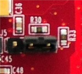
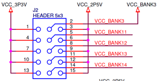
2.“The page 17 Confirm all five J2- jumpers are in place ” “The page 29 EXP Voltage Select” I use DLPLCR95EVN, Where does the short way plug in? if bank voltage is 3.3V, where is the jumper? Where is the position 1?Where is the position 2?
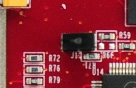
3.“The page 30 J4-APPSFPGA Revision Select”,How do I configure? where is the jumper? Where is the position 0?Where is the position 1?
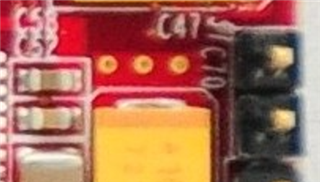
4. In a similar way “ The page 31 J5 J7 J10 ” How do I configure? Where is the position 1?Where is the position 2?


 The default value is 00 - which is NO jumper installed.