This thread has been locked.

If you have a related question, please click the "Ask a related question" button in the top right corner. The newly created question will be automatically linked to this question.

DLPA3005: Behavior of the INT_Z signal

Part Number: DLPA3005

Hi,

I have a question about the behavior of the INT_Z signal in the DLPA3005. I am facing a problem where the INT_Z signal is not working properly.
This signal should go Low when a fault condition is detected, but some devices do not so.

Our tests have revealed the following conditions:
 1. VINA has 12.5V input.

 2. INT_Z pin is externally pulled up.

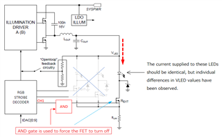
 3. For normally operating device, the output voltage (VLED) value exceeds 11V and INT_Z goes Low.
     For devices operating abnormally, the output voltage (VLED) value does not exceed 11V and INT_Z does not go Low.

 4. Both devices that operate normally and devices that operate abnormally show a gradual drop in voltage as if overvoltage protection has been applied.

 5. When the current value supplied to the ILLUMINATION DRIVER is set to a large value, devices that were operating abnormally will also operate normally.


Why does INT_Z behave this way and what is the difference between normal and abnormal devices?

It is also possible to share INT_Z waveform data. I would appreciate it if you would allow me to private message you if necessary.

Best Regards,
UNA

  • Hello UNA,

    Welcome back to the E2E forum.

    INTZ is an interrupt signal that is typically used to drive PARKZ on the DLPC. PARKZ is used to protect the DMD by parking the device when the DLPA3005 predicts a loss of power. Waveforms for INTZ (PARKZ) can be seen in the power-up and power-down diagrams in the datasheet for the DLPC that you are using. For example, please see Figure 9-1 for power-up and Figure 9-2 for power-down on the DLPC3439 datasheet.

    In your case I suspect that the DLPA is detecting a power rail or output is out of spec. It may be that the controller is attempting to park the device in the normal units as it detects an overdriving of the LED's.

    Can you say why there is a difference on VLED between the normal and abnormal devices? Is this due to a difference in the illumination driver?

    It would be preferable to hold this conversation over E2E so that others may reference this conversation if they have similar questions.

    Kind regards,

    Austin

  • Hi Austin,

    Thank you for your reply.

    The customer's circuit configuration is similar to the figure below.
    Although the same current should flow through the LED, individual differences are observed in the VLED measurement results.
    The illumination driver settings and the LEDs used are identical. Therefore, we would like to know why the VLED observations show differences.

    Note that waveform data is customer-specific, therefore difficult to post on the forum.


    Best Regards,
    UNA

  • Hello UNA,

    We will look into the matter with the details given. We will most likely ask for more information next week to better investigate.

    Regards,

    John

  • Hello UNA,

    I am sending you a friend request to continue this conversation through the direct messages. Please let me know if you do not receive the request.

    Kind regards,

    Austin