This thread has been locked.

If you have a related question, please click the "Ask a related question" button in the top right corner. The newly created question will be automatically linked to this question.

DLP4500: About the reflection of DMD in DLP4500

Part Number: DLP4500

I have a new question.

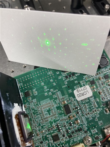
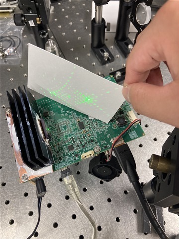
When I irradiate laser beam, the reflection beam spread in a strange way.

Is that OK? Then, the surface of DMD is no matter. If the surface image change, the

spread direction is not changed. Please see the picture.


Is it the bragg reflection .or other diffraction ?

(the laser wavelength is 532nm, power is much low.)

  • Hello User,

    Welcome back to the E2E forum and thank you for this new thread creation.

    I am discussing this question with our optical team and will provide an answer by the end of the week.

    Kind regards,

    Austin

  • Thank you for your reply. If you want more information about my question, please tell me what you want to know.

  • Hello User,

    You are welcome.

    The spread that we are seeing here is the diffraction grating pattern generated by the spacing of the DMD mirrors. Typical optical system designs capture approximately 85% of diffracted light with the remaining light falling outside of the projection lens aperture. The angular spacing of the dots with standard diffraction grating can be calculated by the below equations:

    The mirror spacing is 7.56um. The Green laser wavelength should be 0.52um.

    Regards,

    Austin

  • Thank you so much!

  • Sorry, my question was cleared,thank you. what the difference between left image and right image?

    And,m=M? 

    What the straight line and jagged line about the beam in the left image?

    Is it possible to eliminate light other than m=0?

    why should the green laser wavelength be 0.52nm?

  • Hello User,

    You are welcome.

    When I say the green laser wavelength should be 0.52 nm, I mean this as a recommended value for the lambda in the equation.

    In this image M = m which is the diffraction order.

    Please allow me a couple of work days to respond to the remaining questions.

    Regards,

    Austin

  • Hello User,

    The difference between the two images is meant to show different aspects of the light behavior. The left demonstrates the trigonometry while the right shows angles of diffractions and their order. The straight lines demonstrate the uniform, incoming light while the jagged lines denote diffracted light.

    You may consider reviewing these articles for further information on diffraction:

    https://en.wikipedia.org/wiki/Diffraction_from_slits

    https://en.wikipedia.org/wiki/Fraunhofer_diffraction

    Regarding eliminating higher orders of diffraction, we should keep in mind that the patterns are a result of the narrow band collimated light source (the laser) being the light source. This generates the single wavelength interference patterns. When an LED illuminates the DMD, it acts as a broad band Lambertian light source, ~25nm FWHM, with roughly a gaussian shape. In this case multiple wavelengths overlap and blend our diffraction patterns.

    So, the recommendation for using a laser light source is get this source to mimic and LED as much as possible. For higher lumen applications, multiple lasers are used. Multiple lasers can provide ~5nm wide light source. A diffuser breaks up the collimated wave front where the pattern slit overlaps and blends the pattern.

    Also please keep in mind that 1mW is the safe power rating for eyes. Green laser pointers on the market put out ~40mW of light, so safety measures should be taken.

    Some cheap lasers may not block 1064 nm light. We recommend 520nm semiconductor green lasers. Testing the output with a thermal power meter should provide the safe operational range.

    The below link discusses the dangers of cheap, unfiltered lasers.

    https://blog.everydayscientist.com/?p=2262#:~:text=The%20%E2%80%9Cgreen%E2%80%9D%20of%20green%20laser,the%20green%20532%20nm%20light

    Kind regards,

    Austin