This thread has been locked.

If you have a related question, please click the "Ask a related question" button in the top right corner. The newly created question will be automatically linked to this question.

DLPC7540EVM: Install firmware without USB connection

Part Number: DLPC7540EVM
Other Parts Discussed in Thread: DLP650TEEVM, , DLPC7540

Hi Experts,

Good day! I am posting this in behalf of our customer. 

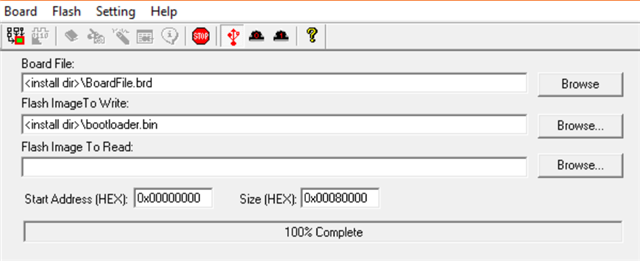
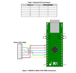
DLPC7540EVM controller for DLP650TEEVM digital micro mirror. Due to poor understanding of disk images (.img file extension), I converted a bmp image into a img image and tried to upload this via the firmware update, thinking it would replace the default logo with my image. However the firmware was erased but not uploaded successfuly, so now my DLPC7540EVM no longer recognises USB and I don't know how to connect to upload the correct firmware. Please let me know how I can install the correct firmware without USB connection (and presumably without any firmware on the controller at all), and how I am meant to correctly upload images (or other binary patterns) to display on the DMD. Thank you in advance for any help.

Best regards,

Jonathan

  • Hey Jonathan,

    In order to communicate with the device other than USB I2C needs to be utilized, which requires additional hardware.

    You can reference section 4.2 of the DLPC7540 Programmers Guide as to how connection can be restored.

    Please come back if there are additional questions.

    Best,

    Aaron

  • HI Aaron,

    Here is the update for our customer and thank you so much for the reponse. 

    Unfortunately I am a bit confused as to how I would go about connecting the I2C to my PC, and will need some further advice. I have an Arduino Uno, would this allow me to connect to the board and upload the firmware? If not, what hardware do I need to connect via I2C? If I am able to successfully connect via I2C, can I still use the GUI to upload the firmware, or is there some other method I must use? If another method, please be as explicit as possible as I am unsure how to write commands to the board without the GUI, particularly if I was to try and upload the disk image via an Arduino.
    Alternatively, is there some way of just resetting the board to factory default, as this would probably be easier to get USB connection back.
    Best regards,
    Jonathan
  • Hey Jonathan,

    For existing designs we have a guide on how to do this. Although, implementation will operate differently with the DLPC7540 unfortunately. I have to work with other members of the team to get this up and running.

    The hardware we utilized is the UM232H Module, which is fairly universal for our reprogramming purposes. Again please give us some time to come back to this.

    Best,

    Aaron

  • Hi Aaron, 

    Thank you for the support. I will be waiting for your update. 

    Best regards,

    Jonathan

  • Hi Jonathan,

    I believe you may have overwritten the bootloader, which may require using a JTAG programmer to fix. A flash programmer tool is found here:

    https://www.ti.com/tool/DLPC900REF-SW

    The tool is for a different board, but you should be able to use it for the 7540EVM if you use the following files instead of the ones that come with the tool as installed:

    https://tidrive.ext.ti.com/u/xjc3u_k3N6_UNzew/180715bb-a4e2-4cbf-9b9b-fd4138373ab5?l

    Replace the appropriate files in the installation directory. The hardware needed can be found in the Help->About menu in the tool.

  • Hi Aaron,

    Thank you for the response. Here is the customer's update below.

    I've had a chance to install the JTAG installer now and just want to confirm exactly what I need to get/do from here:
    The hardware I need is a UM232H module, such as the one found at this online store: https://au.rs-online.com/web/p/communication-wireless-development-tools/7374695
    I also need wires, breadboard and a Molex 51021-0600 (which thankfully I already have)
    The UM232H and the Molex are connected as shown in jtag_wiring.png (attached)

    The Molex is connected to port J20 on the DLPC7540, with each pin matching (i.e. 1 to 1, 2 to 2... 6 to 6)
    The UM232H is connected via USB cable to the PC, and does not need to be programmed/setup in any way
    Start with jumper installed on J9 (not J67)
    Turn the DLPC7540 on by first switching SW5, then SW1 - LEDs D5, D6, D7, D15 and D52 are on (D6 is red, others are green)
    In the JTAG flash programmer, select the board file and bootloader given in the link to the TI drive. (Do I need the FlashDeviceParameters.txt for anything?)
    Set the size in hex to be 0x80000 as per image (not 0x8000, which appears to be the default in the app)
    Click detect chain, and confirm that the box in the GUI changes to indicate a DLPC7540 is connected
    Click erase, and erase all memory addresses in the pop up list
    Click program and then just wait until complete
    Turn the DLPC7540 off by first switching SW1, then SW5, and remove the JTAG connection
    Keeping the jumper on J9, connect the standard USB connection between the DLPC7540 and the PC
    Turn the DLPC7540 back on, and USB should now be detected in the EVM GUI (not the JTAG GUI) for me to upload the correct firmware
    Once firmware is successfully uploaded by GUI, turn off DLPC7540 and move the jumper to J67
    Turn the DLPC7540 back on and the DMD should display the splash logo image
    Best regards,
    Jonathan
  • Yes this looks right, the FlashDeviceParameters.txt in the tool folder probably needs to be updated with the one I provided

  • Hello Jonathan,

    Please advise if you need further information. We'll assume your questions are answered.

    Best,

    Aaron

  • Hi Aaron,

    We still need your help here as our customer has already ordered the UM232H.Here is the complete details of the inquiry below. 

    The UM232H I ordered has now arrived and I have had a chance to follow the steps listed in the last post.

    Unfortunately when I click the detect chain button in the JTAG Flash Programmer, I get the error "Failed to find device information in Board File" when using the board file provided on the forum, and the error pop up does not go away when trying to close it (I have to force quit the application).

    I have tried double checking my wiring between the UM232H and J20 on the DLP board, and I have also tried using an edited version of the board file, where I removed devices 1 and 2 and changed device 3 (the 7540) to be device 1, which gave the same results. The original and edited versions of the board file are attached (edited one is the copy).

    I am not sure how to proceed, but my end goal is to restore the firmware and USB connection to the DLP so I can display images on the mirrors.

    7540 flash files.zip

    Thanks in advance for any help you can provide,

    Best regards,

    Jonathan

  • Hi Aaron,

    Here is the customer's latest update from the customer. Kindly please check.

    I have resolved the JTAG issue, it was most likely due to poor quality soldering or wires touching, so USB connection has been restored now. However I am now unable to upload the firmware to the DLP. When I attempt to upload it appears to load for a bit before I get the following error message:
    Firmware Update Failed.
    'Write Flash Write' command execution failed.
    Error Details: Command Error 0xA - Execution Failed
    I also noticed that unlike the first time I was able to successfully upload the firmware (before losing the USB connection and having to use the JTAG to erase and program), the GUI does not erase the flash at all when I click 'start update' - could this be the issue? Additionally the last two commands in the command log are 'Write Switch Mode' then 'Read Mode', which doesn't make sense to me - why would it try to switch out of bootloader mode before the firmware is flashed?
    I have tried deleting and reinstalling both the GUI and the firmware files, as well as power cycling the DLP, disconnecting/reconnecting the USB and using different USB cables.
    Best regards,
    Jonathan
  • Can you send a screenshot of your attmept to flash the firmware (with the settings shown)?

  • Hi Made4engineering,

    Thank you for asking, Here is the attached screenshot that was provided by our customer.

    attachment (2).zip

    Best regards,

    Jonathan

  • Should not have jumper J9 installed while flashing FW via the 7540EVM GUI

  • Hi Made4engineering,

    Here is the update from the customer.
    According to the controller guide I have attached (which goes through the steps to flash the firmware on the 7540), J9 SHOULD be installed to hold in bootloader mode and program the device (see pages 8 and 10). However to confirm I have also tried flashing with the jumper installed on J67, and with the jumper not installed on either - in all cases the GUI shows the device is still connected and in bootloader mode, with the same errors as previously described. The screenshots would be identical so I have not taken more.
    Best regards,
    Jonathan
  • Are they able to connect UART and get debug messages?

  • Hi Made4engineering,

    Thank you for waiting.

    The customer had been unable to connect via UART and would need some more advice.

    However, without making any changes (as far as we can tell), the firmware was able to successfully upload while we tried to get debug messages. So I'm very confused as to why it suddenly worked but now has a functioning DMD.

    Thank you for your assistance.
    Best regards,
    Jonathan