This thread has been locked.

If you have a related question, please click the "Ask a related question" button in the top right corner. The newly created question will be automatically linked to this question.

DLPLCRC900EVM: connect DLPLCR65EVM with DLPLCRC900EVM

Part Number: DLPLCRC900EVM
Other Parts Discussed in Thread: DLPLCR65EVM, DLPC900, DLPC900REF-SW, DLP9000

Hi Team, 

Good day. I am posting this inquiry on behalf of our customer.

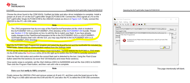
"We just follow the user manual to connect DLPLCR65EVM with DLPLCRC900EVM to conduct a trial following P18-20 of the user manual.

Everything went smoothly but suddenly the software crashed and we cannot connect the board anymore using the GUI. We also found that there are many scratches on the USB port of the DLPLCRC900EVM 

We just order this (Order number T03550518) on 11/17/2022. We cannot accept such qualities that could likely impose unlucky on me.

Therefore, may I know if any technical help or replacement can be executed asap as I have to use this to generate results for my studies?

Thank you."


Please help to advise. Thank you for extending your support.

Kind regards, 

Marvin

  • Hi Marvin,

    I've taken a close look at the board to check jumper configurations, and those look correct based off of the DLPC900EVM Single Chip User Guide. I will refer to this throughout this response.

    I am also very sorry about the condition of the USB port on the board. I will try to support at a technical level for now until more key members come back (Jan 3rd) or if I can find out whether or not we should ship the part back.

    Let's do some quick checks in case it is quicker to troubleshoot than to do a return. Here is a quick list of things I would do a check on just to get the basics down:

    1. Make sure that LED D6 is blinking/showing heartbeat. This shows proper operation of the DLPC900 controller
      1. LED D5 shows a fault has occurred within the DLPC900 controller according to the user guide in Section 1.5 DLP LightCrafter Single DLPC900 Connections
    2. Make sure not to power down the board if the software crashes unless you have a way to park the DMD mirrors
      1. The standby mode is used to relax the mirrors and park them before powering off. This is a two-minute process, and it is recommended to put into standby mode for 2 minutes before powering off.
    3. Make sure external power supply meets criteria for full board operation. I use a 12V, 5A external power supply plugged into a power strip and then flip on the power only once I know everything else is set up correctly.
    4. Check if there are multiple instances of the DLPC900 LightCrafter GUI running. Close all instances and open only one instance if this was true
      1. To close all instances, I like to use the Task Manager for cases here a program hangs/freezes or crashes. This is just a personal thing I do so I am more certain that the whole program has closed.
    5. If the DLPC900EVM controller board was already powered off, please power it back on
      1. Once again, check for the LED D8 and D9 as well as D6 heartbeat before moving on
    6. After restarting the GUI, please select the proper DMD board you are using (DLP6500) in the left-most panel of the GUI
      1. Double check that the system is in normal mode and that the status flags are correct
      2. May I get a picture of the entire GUI after following these steps? Something similar to the second picture the customer provided would be great
    7. If using the same software and firmware package from TI's product page, the firmware should be v6.0.0 and have firmware tag dlp6500_6.0.0_OOB (Out Of Box)

    The board should be functioning at this point if it was just a power problem or a problem with the software crashing or having multiple instances

    If it is not, perhaps we can dig just a little deeper before thinking of a return? I see the customer does not want to worry about it in the future.

    Regards,
    Michael Ly

  • Hi Michael, 

    Good day. Thank you for your prompt response. Please see the feedback from our customer.

    >>>1a. Since the software crash, we have never seen the blinking LED D^6 anymore. We also did not see the lit LED D5.
    >>>3 Specification of the external power supply meets the required 12V, 5A.
    >>>4 We confirm only one GUI was running at the moment.
    >>>5 We confirm only LED D8 and D9 lit. No more lit LED D6 can be observed.
    >>>6 We confirm chip set DLP65 as our selected setting.
    >>>7 Will inform you of the responses to 6a, 6b, and 7 later as the setup is at my other office.

    Please help to advise. Thank you for extending your support.

    Kind regards, 

    Marvin

  • Hi Marvin,

    Please allow time until next week for me to get back to you on this. I would like to discuss this further with another team member who is out until January 3rd.

    Thank you for your patience,
    Michael Ly

  • Hello Marvin,

    Please follow the steps in the DLP® LightCrafterTm Single DLPC900 Evaluation Module (EVM) User's Guide [DLPU101B) note on page 59 under 3.11 JTAG Flash Programming:

    Before using JTAG to reload the bootloader, first install the BOOTHold jumper (J11) and turn the
    system on. The system shows connected, but does not recognize the attached DMD. Manually select
    the radio button that matches your DMD and go to the firmware tab and select the FW image and
    reprogram. Then power down, remove the BOOTHold jumper and restart the system. Reprogramming
    in this manner often recovers a system without requiring reloading the bootloader through JTAG.

    If the firmware has become corrupted (but not the bootloader) then it may not be recognized when the system starts normally, but may recognize the bootloader programming mode when the BOOThold jumper is in place.  If it does not recognize that it is connected at all when the jumper is on, then the bootloader is likely corrupted.

    Fizix

  • Hi Marvin,

    Does the customer still require our support?

    Regards,
    Michael Ly

  • Hi Michael, 

    Thank you for your response. Please see the feedback from our customer. 

    I just got my UM232H
    But, I cannot understand the port 6, 7, and the location of common ground shown in attached figure.
    May I have real photo of the setup so that i can follow to make connection?

    Also, How can we know
    The JTAG programmer has its own copy of the FlashDeviceParameters.txt file which is located in
    the DLPC900REF-SW-x.x.x\\DLPC900REF-JTAG directory of the DLPC900REF-SW bundle. Please
    see Section 3.10 for instructions on how to edit this file to match your flash. If you have already
    made changes to the FlashDeviceParameters.txt file in the DLPC900REF-SW-x.x.x\DLPC900REFGUI\Flash directory that work with the GUI, you may copy that file to the DLPC900REF-SW-x.x.x\
    \DLPC900REF-JTAG directory?

    Please help to advise. Thank you for extending your support.

    Kind regards, 

    Marvin

  • Hi Marvin,

    Here is a photo of our UM232H JTAG programmer: 3V3 is shorted to VIO, and 5V is shorted to USB on the UM232H, as shown in the user manual. I have sent the same images to the customer and will be closing this thread since we have taken our conversation offline.
    Front of UM232H:

    Back of UM232H: (Note: GND is all shorted together, and the solder bridges between 3V3/VIO and 5V/USB.)

    Please make sure the wires coming from the JTAG programmer to the DLPC900 are under 10cm in length to correctly transfer data via JTAG.

    Also, How can we know
    The JTAG programmer has its own copy of the FlashDeviceParameters.txt file

    |
    The FlashDeviceParameters.txt file is located in the *\DLPC900REFGUI\Flash directory, and it contains many lines to determine the flash parameter. Single lines that begin with a '//' Are commented out and ignored when using the FlashProgrammer.exe program inside the same directory.

    The user should take extreme caution when editing the file and when selecting which sectors of memory to write to when using the FlashProgrammer.exe program.

    Here is the default FlashDeviceParameters file for DLPC900REFGUI 5.0.0:

    I used word-wrap so different lines could clearly be seen.

    Before doing that, however, the user should take care and read the top-most section of the FlashDeviceParameters.txt section so they can make the correct decision:

    Regards,
    Michael Ly

  • Hi Michael, 

    Thank you for your response. Please see the feedback from our customer. 

    May I know what should be edited in the FlashDeviceParameters.txt?
    The user manual just said the content should be edited to match the board.
    So, what is the model answer to the edited content?

    Please help to advise. Thank you for extending your support.

    Kind regards, 

    Marvin

  • Hi Marvin,

    The customer should verify which flash chip(s) they have on the DLPC900. To verify which chip they have, they may use the programmer tool as shown below:

    This is an example of the DLPC900 with DLP9000, for example.

    After verifying the MFG ID, the user can then confirm in the FlashDeviceParameters.txt file and comment out any options that are not used and then uncomment (remove the // prepended to the line) the device they need to use.

    If they are indeed using the DLPC900 single EVM bought directly from us, it looks like they have a single flash chip from Spansion? I cannot tell from the image, but there should be an option in the FlashDeviceParameters.txt file for that chip as well.

    Please let me know how it works. Thank you.

    Regards,
    Michael Ly

  • Hello Marvin,

    We are assuming your customer has gotten the help they need.  

    We are closing this ticket for now.  If they still need assistance with this you can respond to this thread in the next 14 days and it will re-open it.  If they need help after it has closed you can start a new thread and point back to this thread for reference.  Thanks you.

    Fizix

  • Hi Fizix, Michael, 

    Thank you for your response. Our customer still needs support. I will update you once we receive feedback from the customer.

    Thank you for extending your support.

    Kind regards, 

    Marvin

  • Hi Marvin,

    No worries, we will be waiting for the update!

    Regards,
    Michael Ly

  • Hi Michael, 

    Good day. Please see the feedback from our customer.

    I tried again the things listed in the user manual corresponding to the inquiry of https://e2e.ti.com/support/dlp-products-group/dlp/f/dlp-products-forum/1183154/dlplcrc900evm-connect-dlplcr65evm-with-dlplcrc900evm.

    The technical issue still cannot be resolved.

    May I know if your company can replace the whole set of items directly?

    Please help to advise. Thank you for extending your support.

    Kind regards, 

    Marvin

  • Hi Marvin,

    Thanks for relaying the information for us. I did a quick check on the pins, and it looks like the customer has wired TDO1 on the UM232H to TDO1 on the EVM connector. The correct wiring should be TDI to TDO1. Here is what I wrote down after taking a look at the connections. Please have the customer swap the two pins mentioned in the picture below.

    The lines I am talking about are below the first long, horizontal black line. The number after the arrow refers to the pin number on the EVM connector.


    I will see if we can replace it if this does not solve it so that the customer has an immediate response after trying it out.

    Regards,
    Michael Ly

  • Hi Michael, 

    Good day. Thank you for your response. Please see the feedback from our customer.

    I followed the comment to repeat the procedure again. Still, the same error comes out.

    I am sorry that I am so frustrated with the board.

    Please help to advise. Thank you for extending your support.

    Kind regards, 

    Marvin

  • Hi again Marvin,

    I talked with Fizix (who also posted in this thread above) about what we are seeing here. Does the customer have the FTDI Drivers installed on their computer with the DLPC900 LightCrafter GUI software? The error message we are seeing may be indicative of this.

    If I could take a second to double check, please have the customer check the following section of the DLPC900 Single EVM User Guide in the following section and verify they have the FTDI driver installed before trying again. Additionally, please ensure the lines from the UM232H to JTAG interface are shorter than 10cm. It looks like the lines they are using may be longer than that, which may result in unreliable data.

    Best regards,
    Michael Ly

  • Marvin,

    The customer and I have decided to take things offline and will be closing this thread. Due to the customer's unique circumstances, we have decided to replace their DLPLCRC900.

    Regards,
    Michael Ly