This thread has been locked.

If you have a related question, please click the "Ask a related question" button in the top right corner. The newly created question will be automatically linked to this question.

DLPDLCR2000EVM: PDATA[0-15] 16bit configuration in DLPEVM for RGB565

Part Number: DLPDLCR2000EVM
Other Parts Discussed in Thread: DLPC2607

Tool/software:

Hello,

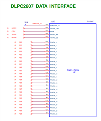
I'm working on connecting my application processor to the DLPDLCR2000EVM to transfer parallel data. I have connected the DATA0 pin of the application processor to the DATA0 pin of the DLP EVM and similarly connected all the pins in an orderly manner. 

Here's the connection mapping: DATA0 corresponds to DATA0 on the DLP EVM, DATA1 corresponds to DATA1 on the DLP EVM, and so on upto DATA15 to DATA15.


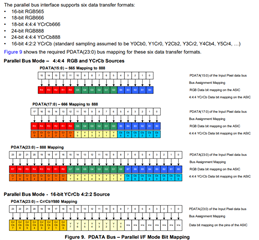
Could you explain how the DLP EVM processes RGB565 data in this parallel format? We would like to know which specific pins the DLPDLCR2000EVM uses for the R (Red), G (Green), and B (Blue) components when processing RGB565 data in parallel format. Can you clarify the mapping for each color component?

Because we are getting different colors in projection.

In software, we performed the below i2c communications only.
1. Input Source Selection: Parallel source :- 0x0B 0x00 0x00 0x00 0x00
2. Input Resolution Selection - nHD 640x360 :- 0x0C 0x00 0x00 0x00 0x27
3. Pixel Data Format - - RGB565 transferred on a 16-bit bus - 0x0D 0x00 0x00 0x00  0x00

Is my connection right? Please share your suggestions.


  • Hello Texas,

    I wanted to follow up on my previous inquiry regarding how the DLP EVM processes RGB565 data in parallel format. Specifically, we are looking to understand the pin mapping used by the DLPDLCR2000EVM for the R (Red), G (Green), and B (Blue) components. Could you clarify which pins correspond to each color component when processing the RGB565 data?

    Have you had a chance to look into this?

    Your assistance would be greatly appreciated.

    Regards,
    Manikandan

  • Hello User,

    Sorry for the delayed response due to the Thanksgiving Holidays in the United States. 

    Please check out the following from section 7.3.1 of the DLPC2607 datasheet. www.ti.com/.../dlpc2607

    Regards,

    Alex Chan

  • Hello Alex,

    Thank you for your response.

    We connected the RGB565 data (PDATA15:0) from the Application Processor to the DLPEVM as described in the datasheet but observed that the red and blue channels getting swapped. 

    To address this, we modified the connections as shown below. With this configuration, the red, blue, and green channels are projected correctly, and we could also able to reproduce other colors as well. 

    Red       -   F8 00 (R: 11111, G: 000000, B: 00000)
    Green   -   07 E0    (R: 00000, G: 111111, B: 00000)
    Blue  - 00 1F (R: 00000, G: 000000, B: 11111)

    Could you please share your thoughts on this?

  • Hello User,

    The team will have to look into this further.

    I checked our reference schematic and we have the following connections:

    How is the application processor sending the RGB data?

    Regards,

    Alex Chan