This thread has been locked.

If you have a related question, please click the "Ask a related question" button in the top right corner. The newly created question will be automatically linked to this question.

LIghtCrafter Flexible Trigger Configurations

Other Parts Discussed in Thread: TPS60150, TPS63020

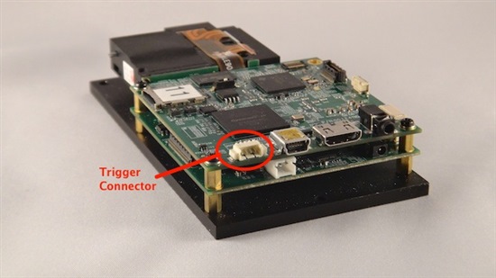
LightCrafter offers several flexible trigger configurations. The trigger connector (J7) lies at the back of the System board (top board):

The pinout of J7 connector is:

  • Pin 1 - Tigger Supply
  • Pin 2 - Trigger Input
  • Pin 3 - Trigger Output
  • Pin 4 - Ground

Two matching four pin mating connector part numbers are:

  • Molex part number: 51021-0400
  • Digi-Key part number: WM1722-ND

The corresponding crimps part numbers are:

  • Molex part number: 50079-8000
  • Digi-Key part number: WM1142CT-ND

LightCrafter's J7's trigger input and output pins are level translated or shifted to and from the I/O supply of circuits in the System board. Out of the factory, the output trigger signal is level shifted from the 1.8V I/O supply used by the System board FPGA to 3.3V. Below is a snapshot of the schematic of these circuits. U20 level shifts the trigger input. U23 level shifts the trigger output. Note that the supply on one side of these level shifters is tied to the internal 3.3V supply, while the other side is tied to 1.8V.  The level shifter are open-drain outputs with internal 10Kohm pull-ups.

In this schematic, a resistor with a value of NA_0 indicates the resistor is not populated. A resistor value of 0 indicates that a zero ohm resistor is present.

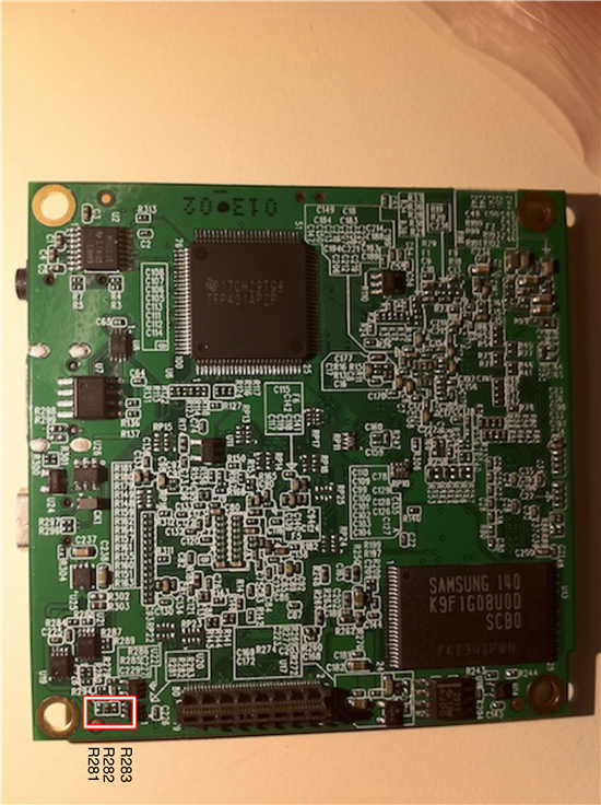
If an external 5V trigger signal is desired, then the LightCrafter board must be modified to input an external supply and use that as the level shifter input voltage, as follows:

  • Install zero ohm resistor R285
  • Remove zero ohm resistor R282

Then supply the external trigger voltage through Pin 1 of J7 (EXT_TRIG_VCC) and the external trigger through Pin 2 of J7 (TRIG_IN_CON).

  • Hi Pedro, I need some help interfacing a 5V MCU with the LghtCrafter Trigger inputs.

    I would like to know if there is a simpler way of doing it, without modifying the system board.

    I couldn´t find the R282 0ohm resistor. Where is it?

    Thanks

  • Enio,

    Unless you have a level shifter on the MCU to change the 5V signals to 3.3V, you will have to modify the board. 

    R282 is in the back of the SyStem Board (top board). It is in the group of three resistors that has a label next to the daughter card connector. It is between the daughtercard connector and screw hole, next to a ground test point.  R282 is the middle resistor. 

    See the bottom left corner of this photo:

  • Pedro, I have a few quiestions about the trigger signals:

    1. Which is the treshold voltage for 3.3V and for 5V?
    2. Can I power a circuit from the EXT_TRIG_VCC pin, how much current can I source
  • Enio,

    The threshold voltage for TRIG_IN_CON is handled by the TXS0101. From its data sheet, the Vil is 0.15V and Vih is Vcc - 0.2V where Vcc is the EXT_TRIG_VCC. Vcc can be anywhere between 2.3V to 5.5V.

    You can power a circuit from EXT_TRIG_VCC. The amount of power is dependent on how much is consumed on the LightCrafter and the supply that is sourcing it. For instance, EXT_TRIG_VCC supports, 1.8V, 3.3V, and 5V options.

    • On default configuration of LightCrafter, the 5V supply is sourced from USB VBUS. So there is very little 5V current consumed in the system and the budget is dependent on what the USB port provides. On this supply, there is a TPS60150 (U25 in system board), but it is disabled and the P5P0V supply is disconnected from SYSPWR (the LightCrafter power input).
    • The 3.3V supply is sourced from the driver board TPS63020 (U15 in driver board) that has a max output current of 3A. However, this supply is used for most of the LightCrafter devices. So a significant budget is consumed, but it is not the majority of this supply. To provide an example when LightCrafter is operating at the 20 lumen value (LED set to 274), the overall current consumed at SYSPWR is about 700mA. This includes all the supplies including the LED drivers that use 600mA.
    • The 1.8V supply is sourced by the TPS650531 (U15 in system board) has a max rating of 1A.  This supply is shared with some DM365 analog and DDR2 I/Os, as well as, the DDR2 RAM so a few 100mA's are consumed when the DM365's external RAM is heavily used. 

    Note that the overall power budget is limited by the power supply into the LightCrafter system. This typically ranges between 2-3A. As you can see, there is enough current available on these supplies to power at least 100mA external circuit.

  • Thank you for the response Pedro.

    I have a few more questions:

    1. I'll be powering a circuit with 3.3 V, to do that I have to solder  0 ohm resistance R285 or R295 (please correct me if I'm wrong). Are these also located in the back of the System Board?
    2. Is there any conection to the 3.3V power source of the lightcrafter, that does not require a modification to the board.?
    3. Do you have the digikey part number for this 0 ohm resistors?
  • Hi Enio,

    You will have to install 0 ohm resistor at  R295,  which is on the top of system board (above the J7 connector).

    Here is the part number for 0 ohm resistor we used:

    Digi-Key part number: P0.0AGCT-ND , Manufacture part number: ERJ-1GE0R00C

    Could you please tell me how much current would the external circuit consume?

    Please be aware of the current you can source from this pin. (Refer to Pedro's post above).

    Regards,

    Divya

  • How would I be able to achieve a flexible output trigger configuration?

    Industrial cameras currently use triggers of different voltage (e.g. Point Grey Flea 3V and IDS Imaging uEye 5V).

    My idea would be to either move the zero-ohm resistor from R292 to R295, and source the appropriate trigger voltage from the camera itself, as most cameras provide some current at the right voltage.

    The alternative would be a three position microswitch installed over R291, R292 and R293. Does anyone have experience with this and can you recommend a part that could be soldered directly onto these positions?

    As most newer cameras use opto-isolated trigger ports, I wonder if one of these solutions offer an advantage in terms of current to drive the opto-isolated circuit? Also in the application note for "Imaging Source Cameras", it is suggested to output the trigger on pins 1 and 3, which reverses polarity. Does this mean more current?

    Regards,

    Jakob Wilm

    Technical University of Denmark

  • Hi Jacob,

    We have tested the scenario mentioned in white paper i.e, externally triggering the LightCrafter by installing 0 ohm resistors at R292 and R295. But if your camera is capable of sourcing appropriate trigger voltage and current, you can apply idea 1 (U23 is an open-drain level shifter)

    Unfortunately, I am not aware of a three position switch. LightCrafter E2E community might be able to help you.

    Regards,

    Divya

  • I have a question regarding triggering a Ximea camera with ~20V input level.

    Details are found here: http://www.ximea.com/support/wiki/usb3/Digital_Input

    Now, unfortunately, the LC does only support 1.8, 3.3 and 5V output configurations. Would there be a simple component such as a step-up converter that allowed me to trigger a camera from Ximea?

    Best regards,

    Jakob

  • Jakob,

    The Ximea camera doesn't require ~20V, it will operate with signals as high as that. The trigger input is an optical isolator. This is pretty much standard on all cameras with trigger inputs. The internal LED requires current - around 10 mA. The DLP LightCrafter and DLP LightCrafter 4500 can be used for these trigger inputs.

    See:

    http://www.ti.com/litv/pdf/dlpa032 Using the DLP® LightCrafter™ to Trigger CCD Cameras from The Imaging Source®

    http://www.ti.com/lit/an/dlpa036/dlpa036.pdf Using DLP® LightCrafter™ 4500 Triggers to Synchronize Cameras to Patterns

    The LightCrafter trigger output cannot source current, so see the App Note DLPA032 for the correct connection using VCC.

    LightCrafter 4500 can source current from its trigger outputs. See DLPA036 for more information.

  • Hello Pascal,

    according to Ximea specifications the "ON" state is defined between 15 and 30V. See http://www.ximea.com/support/wiki/usb3/Digital_Input . I have just verified this using a function generator. The camera triggers reliably on pulses of about 12 V.

    As far as my understanding, the document above describes a modification that is necessary when the camera draws to much current, but the trig signal would still be at 3.3V (or 1.8 or 5). In fact, the Imaging Source cameras are specified for 3.3V, see http://www.theimagingsource.com/en_US/blog/posts/20080603/ .

    Have you verified that Ximea camera triggering works on the LC? I can't seem to make it work.

    Regards,

    Jakob

  • Jakob,

    No - I have not verified the Ximea camera triggering on the LC. I have never seen a Ximea camera. Looking at the schematic and details from Ximea (http://www.ximea.com/support/wiki/usb3/Digital_Input) it appears that what you are saying is true. The "on" state goes from +15V to +30V. This is not like oher optoisolated camera triggers which I have seen, which usually work as low as 1.8V.

    This means that you will have to insert a level shifter between the LCr trigger output and the camera trigger input. The LCr trigger signal is "open drain", which means that it can sink current, but it cannot source current. That means that it requires a pull-up resistor in order to provide a logic level. However, the maximum volatage which can be applied to the pull-up resistor is +5.5V. See the data sheet for the TXS0101DCK ( http://www.ti.com/lit/ds/symlink/txs0101.pdf ).

    Also, see the LightCrafter documentation, which includes the schematics of the Driver Board and the System Board. The triggers are on the System Board schematic, page 13.   DLP LightCrafter EVM Design Documentation  http://www.ti.com/LCRdesigndoc,

  • Hello Pedro,

    We also need to have a 5 V TTL trigger signal to the LCr or vice versa. The connector of the external device is DB-15 D-sub (with pins described below). All the seven I/O pins have 10Bit 0-5V DC A/D

    Would you, please, help me in figuring out which pins of the trigger connector should be connected with which pins of the external device. Another issue is that after reading in the forum for users having damaged their LCr during soldering, I prefer to make this offset somehow externally. Does TI produce some level shifters that might be easily integrated without modifying the board in order to work for us?

    I looked for the resistors you specify, i.e. 282 and 285 but on our board are present 292 and 295 near the trigger pins. Are these the same?

    Thank you in advance for your assistance.

    Kind regards,

    Jordanka

  • Jordanka,

    You would use a couple of the pins configured as General Purpose (GP) pins: pin 1, 2, 3, 4, or 7. This connector seems to be from a servo motor. So the pin selection depends on your use. 

    From LightCrafter you have a trigger input and a trigger output. Depending on your use, you could have the trigger output connected to one of these GP pins set as an input.  And another GP pin setup as output connected to the trigger input. Depending on your use you might only need the trigger output. For example, the LightCrafter in internal trigger mode will display a pattern and the LightCrafter's trigger output goes high to indicate that a pattern is displayed and this is captured by the servo motor GP input. On the other hand, you could have the motor send a high signal to indicate the LightCrafter to display the next pattern by using an output of the servo motor in GP mode and setting the LightCrafter in external trigger input. The servo motor needs to toggle this pin high to advance patterns.

    Since the LightCrafter is setup for 3.3V I/O out of the box, the LightCrafter 3.3V trigger output could drive the input of this servo motor since most 5V TTL signals need 2.0V or higher to detect a high signal. However, you cannot drive a 5V signal (an output form the servo motor) into a 3.3V logic (LightCrafter's trigger input). Thus, do not connect a 5V signal to a LightCrafter input without adding a level shifter or changing the resistor values. 

    For a 5V trigger input, remove R282 and short across R281 to set the input level shifter to 5V.  These are present on the bottom of the board next to the screw and trigger connector.

    For 5V trigger output, remove R292 and short across R291 to set the output level shifter to 5V. These are present on the top of the board next to the screw and trigger connector.

    I have not seen a simple EVM from TI that just performs level shifting between 3.3V and 5V. I know Spark Fun, NCK Electronics, and Total Phase have level shifter/logic converter small boards. Spark Fun had one that was about $2 and was breadboard friendly. 

    Best regards,

      Pedro

  • I would like to get 5V trigger output.  According to the procedure above, I need to remove R292 and short across R291. 

    I have two questions:

    First, it seems R292 in my board is already open. I don't know why. Is that normal?   

    Second, in order to short across R291, can I just solder it instead of placing a zero ohm resistor?

    Thanks,

    Boyuan


  • Hello Boyuan,

    No I think it is not normal. Can you confirm at least one of three resistors R291 or  R292 or R293 installed? 

    By default the trigger o/p selection switch should be set to R292 3.3V o/p. 

    Anyways, yes, for 5.0 trigger o/p you can install 0-Ohm @ R291 pad location. Ideally you need to install the resistor but shorting can also work. Also make sure only one of three resistors installed.

    Regards,

    Sanjeev

  • Hi Sanjeev

    Thanks a lot for your reply. You are right.  By taking a close look with a magnifier, R292 is currently installed.

    I think I need another advice from you on how to remove the resistor from the board (e.g. brute force or some special tool available). Since I have never done this before, a detailed description would be highly appreciated.

    Best,

    Boyuan 

  • Hi Boyuan,

    Best way would be to take it to board shop or electronic repair shop and ask them to do the modifications. 

    Regards,
    Sanjeev