


Hi
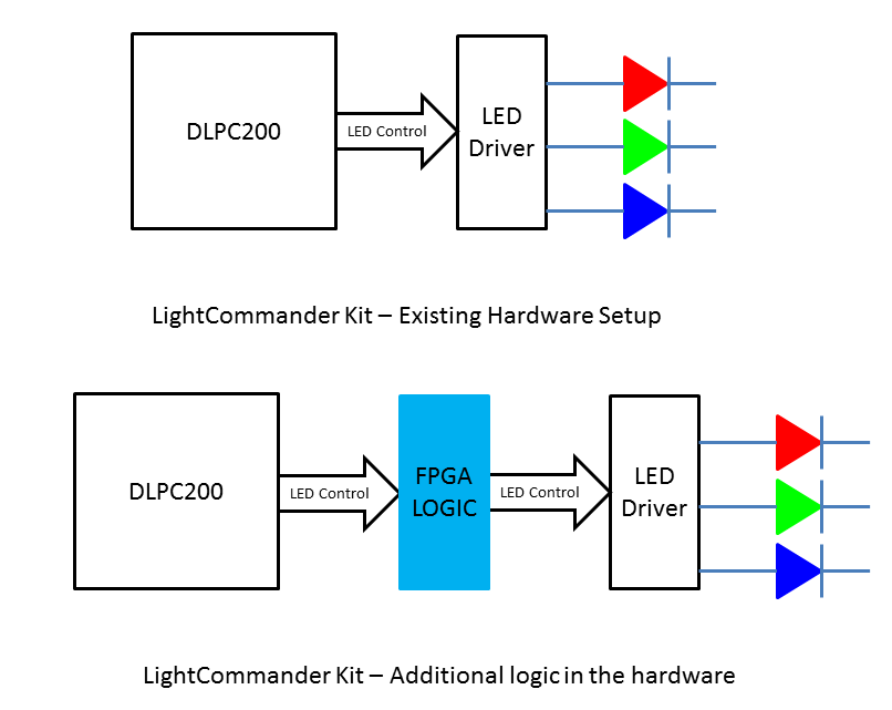
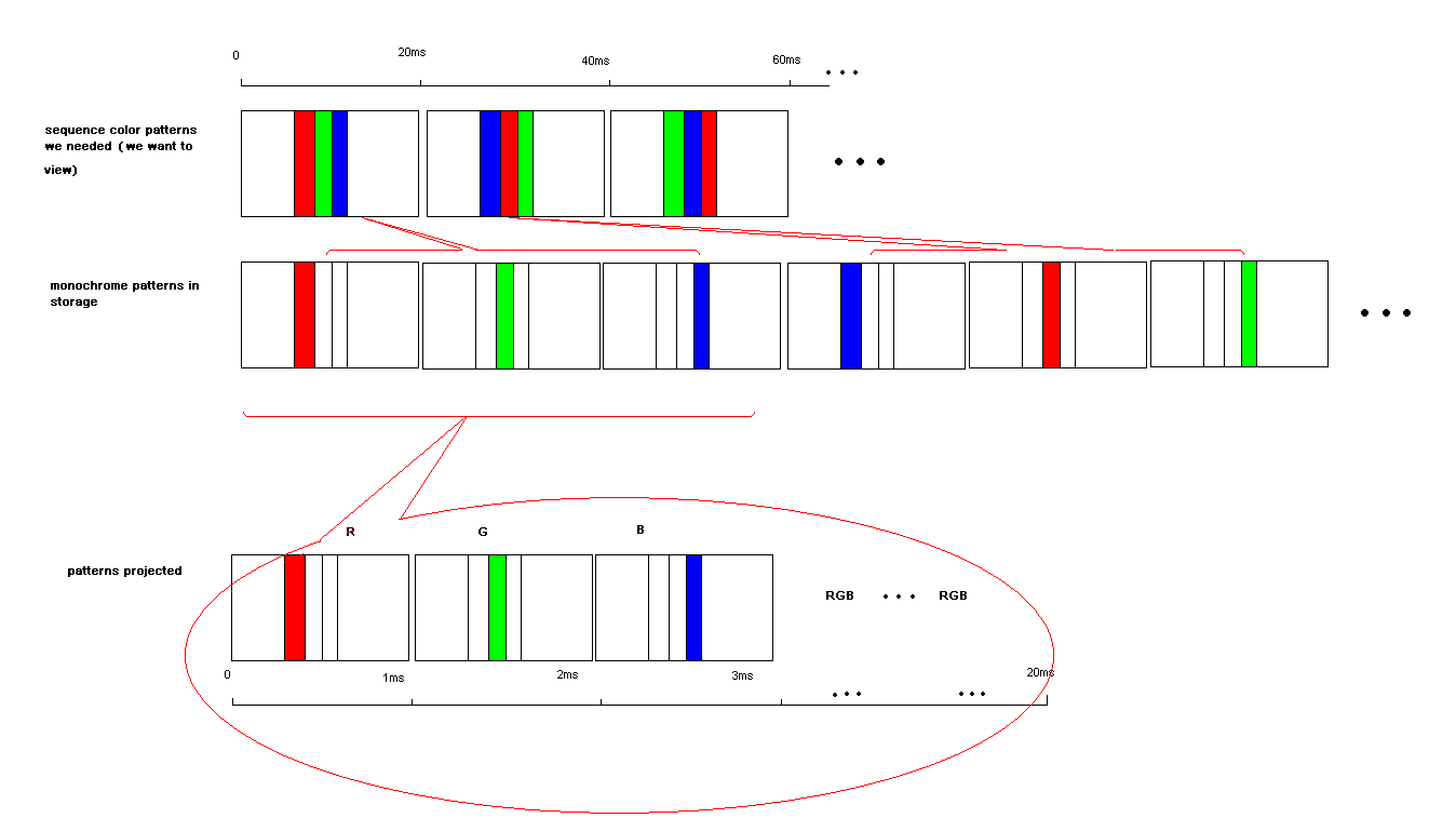
We are planning to use LightCommander for 3D Optical Metrology Systems. I want to know whether Lightcommander can project color pattern in Structure Light Mode. If can't, is there any other way to project color pattern?
Thinks.
Hi
We are planning to use LightCommander for 3D Optical Metrology Systems. I want to know whether Lightcommander can project color pattern in Structure Light Mode. If can't, is there any other way to project color pattern?
Thinks.


