This thread has been locked.

If you have a related question, please click the "Ask a related question" button in the top right corner. The newly created question will be automatically linked to this question.

DLPC150: 24-bit Binary Display to DLP2010NIR

Part Number: DLPC150
Other Parts Discussed in Thread: DLP2010NIR, , DLPA2005

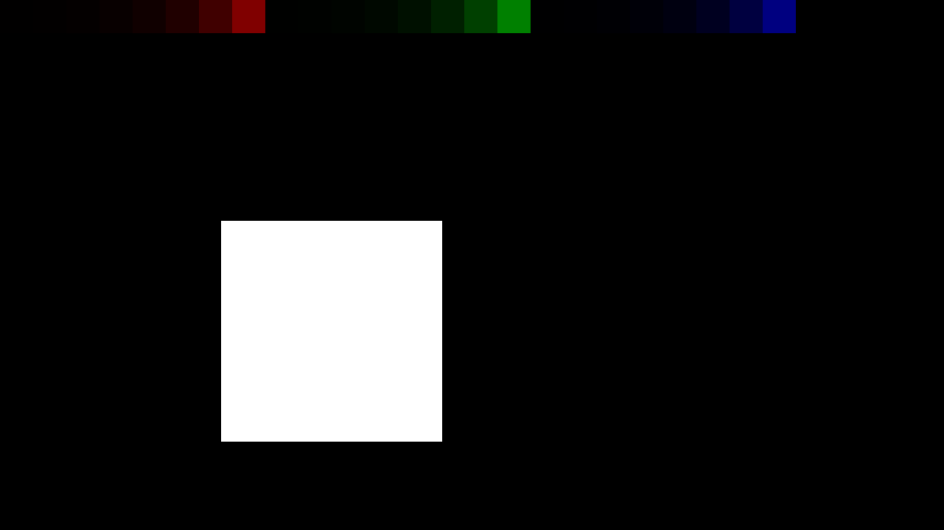
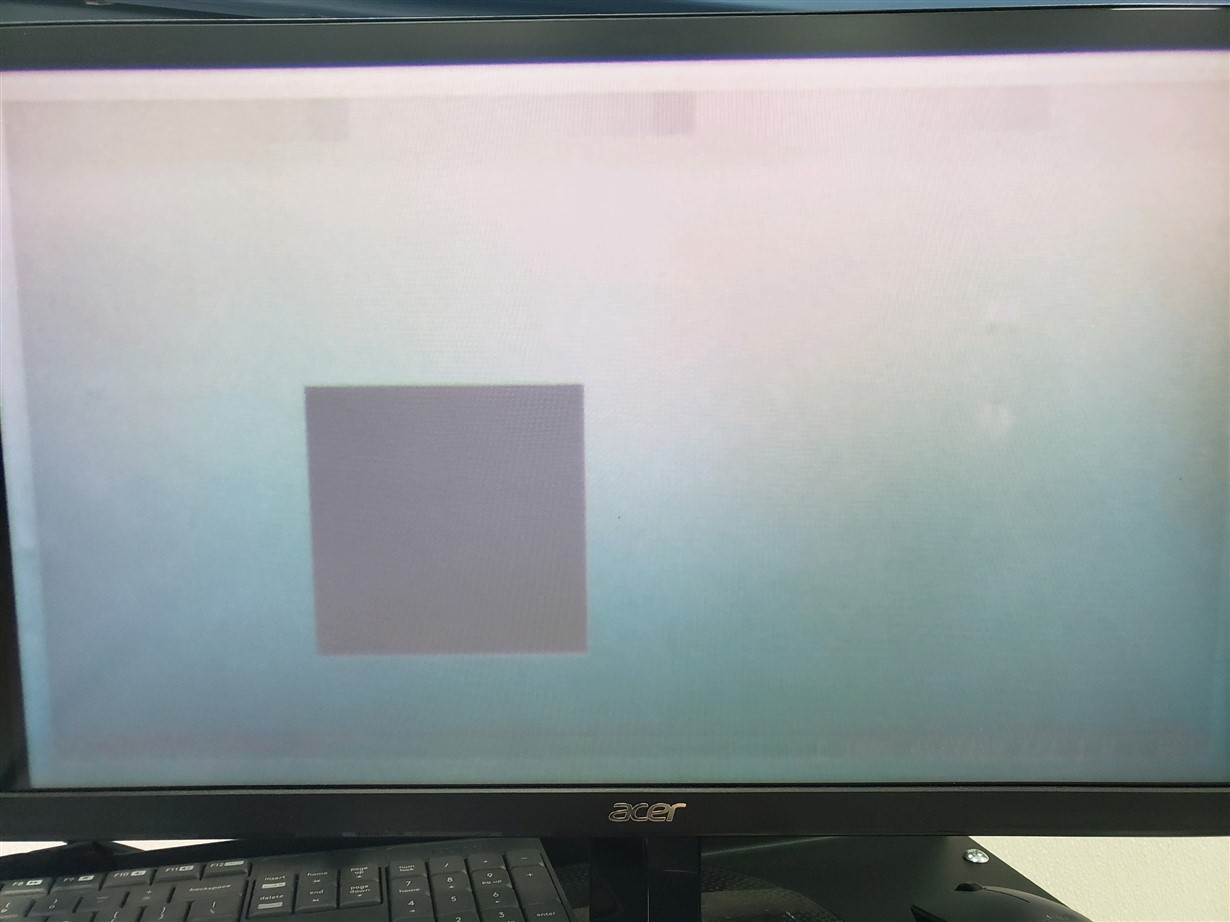
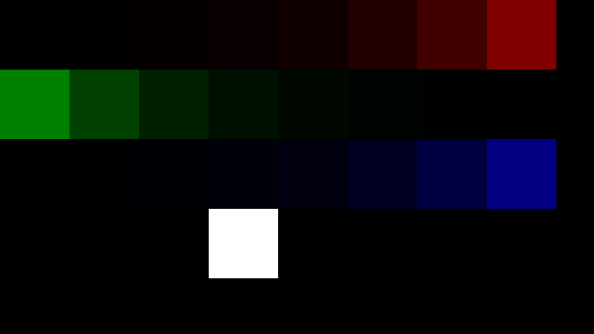
I am trying to get 2880 Hz binary pattern display using 24-bit parallel with the dlpc150 and dlp2010nir.  In section 8.1 of the DLPC150 datasheet "Pattern Generation Mode" is described as the way to reach the advertised 2880 Hz binary pattern rate.  However, the phrase "Pattern Generation Mode" isn't described in the programmer's guide.  Using 60 Hz Display with 24-bit parallel I attempted to get a test image to display a pattern at 1440 Hz.  To do this I used "Command Number" 0xF5 to setup the display sequence to auto mode as described in section 2.5.3 of the pg.  However it appears that the dlp2010nir isn't displaying binary patterns and is instead displaying the color interpretation of the 24-bit image.  I have attached the test image and how it visually displays on the dmd under a microscope.  The expectation was that the top row of squares should show visually with the same intensity since they are each given 1-bit in 1 color and should each therefore be on with a cycle of 1/24.  I'm starting to think that in order to get binary pattern mode I must use the external trigger input mode as described in section 2.5.4 of the pg instead of auto mode.  Since our hardware is not configured to support external trigger mode I wanted to make sure that I'm not missing something else before we commit the time and resources to modify our hardware to test external trigger mode.

Test Image

Visual result under a microscope

Again if binary patterns were being displayed we would expect constant intensity in the upper row of squares.  The microscope results are shown on a 60 Hz monitor and the exposure time and intensity were adjusted until there was no visible aliasing.

  • John,

    Welcome to the E2E forums and thanks for your interest in our DLP technology.

    If I understand your question, the concern is that the squares above should appear all at the same intensity, right? Given your pattern above, it depends on the encoding of the data within each square what bits will show up at the output.

    Have you tried measuring the output of each square with a photodetector to capture the content of each section of the image with regards to what bits are being represented? This would be helpful information.

    What sort of illumination source are you using?

    Regards,

    Philippe Dollo

  • Philippe,

    Yes, the main concern is that the visual inspection of the mirrors seems to make sense if the 24-bit parallel encoding represents color instead of binary images. for each color in the band of squares the intensity is 1, 2, 4, 8, 16, 32, 64, and 128 from left to right.  The DLP2010NIR has a white light shined on it that is inspected with a microscope.  We are able to see a good amount of detail doing this (we have tested other images as well) although it was difficult to capture in the photo taken.  I can try to take a higher quality picture tomorrow, but we can pretty easily determine without the use of a photodetector that the 128 value squares are on substantially longer than the squares with other values.  The most likely cause seems to be that we are somehow missing some configuration to change from color to binary display although I can't seem to find such a setting explicitly discussed in the programmer's guide.  Also, we were actually able to hook up a pin and drive the external trigger at a constant 350 us low and 10 us up (command 0xF6 from section 2.5.4) and got very similar display results compared to automatic mode.  It seems like you might be suggesting that we aren't quite seeing what we think we are seeing, although I am somewhat confident that this is not the case I will see what I can implement tomorrow to try to improve our inspection of the mirrors.

    Thanks,

    John

  • Maybe this helps explain what we are seeing.  The brightness of the bulb was turned to the maximum so the auto exposure would become as short as possible and creates the aliasing pattern.

  • Hello John,

    Thank you for sending this video. You can expect a team member to get back to you by EOD 2/26.

    Regards,

    Austin

  • John,

    Thanks for sharing the video. What frame rate is this running at? 

    It does look like the intensity of the different sections of the image does not add up. Are you using the same sequence of commands in the DLPC150 programmer's guide, ending in 0xF6?

    If so, have you tried using an internal pattern streaming command to compare against your setup? Are you seeing similarly incorrect results?

    Regards,

    Philippe

  • Philippe,

    The display of the microscope output is running at 60 Hz.  The display to the dmd over 24-bit parallel was 120 Hz.

    We have tried several different command sequences I believe at one point we tried exactly replicating the commands in table 2-46 and the commands in table 2-47.  I will double check running those command lists exactly later today.  The test pattern generator seems to behave properly, we have tried a few different test patterns without any issues.  If you meant loading a test pattern into flash memory and streaming from there we have not tried that.  Is there a specific test that you would like to see?

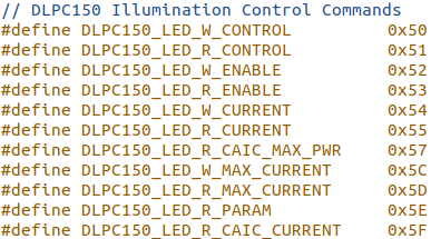
    I have another related question about the DLPC150.  I have been looking through the DLPNIRscanNanoSoftware for any hints about what is missing and I came across several commands that I didn't find in the programmer's guide.  Is there information anywhere on these commands that I can get access to?  Also where should I look to determine the relationship the dlpa2005 has to the dlpc150 and dlp2010nir specifically with regard to pattern streaming mode / normal mode.  This application is for sensing only and doesn't need projection.


    Thanks,

    John

  • John,

    If you are able to try to perform internal pattern streaming to see if the intensity of each bit is as you would expect (with a photodetector) that might be helpful.

    With regards to your other question about the commands above and the integration of the DLPA2005 into the chipset, I'll need to consult with the team so we can give you a more thorough answer. Expect a response early next week.

    Regards,

    Philippe Dollo

  • Philippe,

    We are currently unable to setup a photodetector with the IR optical assembly yet.  I think I may have made some progress though.

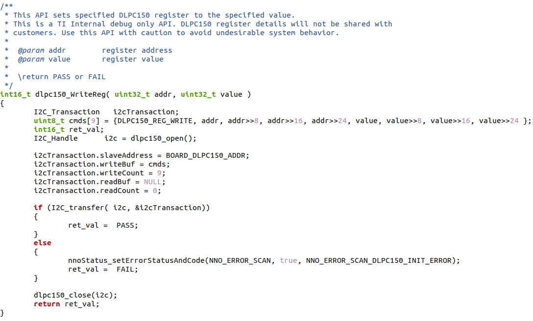
    I found an interesting line in the DLPNIRScan software where they setup pattern mode after they apply the sequence from table 2-47 in the programmer's guide.   When I added this line to my own code it seems to have made us enter pattern mode although there is still some unexplained issue where some boxes are still different intensity.  See below for the code section found and a clip of what happens to the mirror when this is applied.

    Here is the pattern applied in the video.

    I can't find information on this from ti so it seems that we need some additional documentation that isn't publicly available to change to pattern mode.  Is there anyway to get access to this?  I plan to try implementing exactly what the code from the DLPNIRScan is doing to see if I can iron out this last part.

    Thanks,

    John

  • Hello John,

    Thank you for the information above. We are investigating your issue and appreciate your patience as we are looking for solutions.

    Regards,

    Austin

  • John,

    Based on a review of the software, it appears that you shouldn't need to configure anything on your end to ensure the bits of the image you are looking at are "equally weighted". Unfortunately, however, the nirScan Nano is designed to be controlled by the TIVA controller so you may run into some difficulties trying to implement functionality manually.

    For now, I recommend you start by using a photodetector if possible to identify the sequence that is running on the system (which also removes image processing and image data from your frontend from the equation).

    Regards,

    Philippe Dollo

  • John,

    Any updates per the above?