This thread has been locked.

If you have a related question, please click the "Ask a related question" button in the top right corner. The newly created question will be automatically linked to this question.

DLPDLCR2000EVM: Sync resistors & Power supply ringing questions

Part Number: DLPDLCR2000EVM
Other Parts Discussed in Thread: DLPC2607, TPS62260, DLPA1000, DLP2000

Hello again,

     I'm playing with the 2000EVM on a Beagle Bone Black (direction connection) and had a couple of design questions for you.  The first pertains to ringing caused by the V_Sync and H_Sync pulses.  There don't appear to be any limiting resistors between the Sitara AM335x and the DLPC2607 -- and I couldn't find any mention (I could have missed it) in the datasheet for the DLPC2607 indicating how the HSync and VSync inputs are tied to the power.  But the Sitara mentions that it can sink 6mA, and by the looks of the ringing in the signals, it sure is trying.


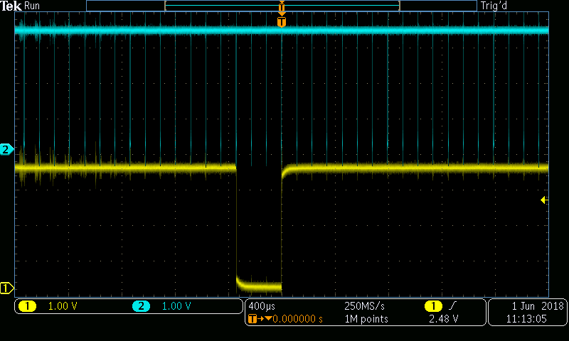
(VSync, Channel 1, Yellow) (HSync, Channel 2, Cyan)

So I next hooked up channel 2 to the VINTF supply and triggered off of the VSync signal (still channel 1), and saw the ringing made it through to the supply line.

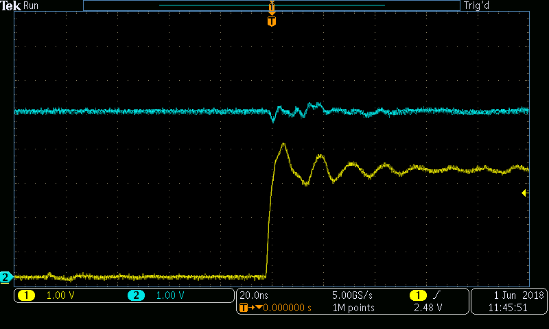
That seemed like a lot of ringing -- so I went one step further.  I wanted to know how much power-line ringing would cause a problem.  And the answer is -- not a lot.  I issued the I2C commands to stream-out the BBB display, and then injected a similar signal into the power supply line as the one I saw above.  It didn't long to cause a reproducible reset condition (Lightcrafter display would blank, then show splash screen).  I would then resend the I2C commands to reset the display, and send the pulse, and it would turn off.  Worked a dozen times in a row, so I stopped trying.   BBB was provided the same power input and stayed on.  (So the boards had the same ground reference).  And just to clarify -- the cyan above is VINTF, and they yellow below is DCIN.

So really, I suppose I have a few questions:

1)  Why didn't the engineers use any current limiting resistors (or damping/snubbing) on the sync signals?  Was it intentional or an oversight?

2)  What is causing the display to reset?  There is one LDO, two step-down converters (TPS62260), and the DLPA1000 Asic -- all of which have output voltages that are much, much less than the input, and I would think would be immune to an incredible amount of noise -- certainly more than I provided here.

3)  Am I missing something?

Thanks,

Mark

  • Mark,

    Typically, it is expected that the current limiting resistors are placed at the driver side of the network for matching purposes. I believe it is for this reason that we opted to leave them out in this EVM.

    As for the resetting behavior you are seeing, I will see if I can investigate the behavior and get back to you within a couple of days.

    Best Regards,
    Philippe Dollo
  • Thanks Phillipe,

         While you've got your scope out -- you should look at the RGB888 signal lines as well.

    Unfortunately, I don't know that the Beaglebone folks (whoever they are) always know what is going to be plugged into their board -- so in this case, I believe the onus is on the TI engineers who made the cape.  (I'm not trying to give them a hard time -- it's a really, really neat application -- and you can't beat it for $100.  I know this level of engineering acumen is beyond my current capabilities.)

    If you do respin the board -- you might want to also adjust the cutout so it fits a BBG.

    I'll keep this setup on my workbench for the next week or so in case you need more details or measurements to recreate the condition.

  • Hi Phillipe,

         I hope you've had a wonderful week.  Did you happen to have a chance to look into the ringing issue on the signal lines?  Also, will you be attending Sensor Expo in San Jose at the end of the month?  Perhaps we could schedule a meeting.  I'd be happy to buy you the best burger that the food-court has to offer (provided it's less than $15, of course).

         Anyhow, the article I wrote is ready for publication and will go live sometime next week:  If you have any comments, you can leave them here, email me, or comment in our forums.  I'm happy to look into your other lightcrafter kits as well if you like.  You can direct your marketing folks towards me at mark@allaboutcircuits.com.  Perhaps I can dive deeply into structured light sensor usage

    Thanks,

    Mark

    Technical Writer / Technical Editor

    AllAboutCircuits.com

  • Mark,

    Thanks for your update.

    Unfortunately, I have been preoccupied with business overseas, so I have been unable to follow up on your inquiry until now. I'll forward your information for sure, and while I'm at it I'll see if I can sit down this week with the DLP2000 to characterize the latest revision.

    Thanks a lot for your attention.

    Best Regards,
    Philippe Dollo
  • Thanks Phillippe,

         I do understand how life can get busy.  I'm just now back from Sensor Expo in San Jose and it's probably time that I push this article out for publication.  If you see any errors/omissions/etc... please let me know, I'm happy to fix them.  Also -- if you want me to play with any of your other lightcrafter EVMs, I can be reached at mark@allaboutcircuits.com

         Also -- please feel free to pass my contact information along to any other application engineers you know -- I work with whatever technology floats my way.

    Thanks,
    Mark


  • Mark,

    I've had some time to review the system, and the ringing you characterized above appears to be reproducible on my system as well. In particular, I am seeing about 1.4 V of ripple on the Hsync/Vsync lines, and approximately 300 mV of ripple on the Vintf line. For the time being I won't supply the scope captures I grabbed as they appear to match yours pretty closely.

    Unfortunately, this means that current-limiting resistances will need to be added to the system for a custom design (outside of the prototype phase). Of course, for mobile applications we tend to recommend more compact, robust protocols such as DSI (as with our 343x platform) when available.

    Thanks a lot for your attention! Please don't hesitate to ask if you have further questions.

    Best Regards,
    Philippe Dollo
  • Thanks Philippe,

         Have a good day.

    Mark

  • Phillippe!

         I completely forgot about the reset question.  I know that one's a little harder to initiate.  But do you have any idea what happens in the circuit to cause it to restart when the power supply rings?

    Thanks,

    Mark

  • Mark,

    There is a voltage monitor within the system which will prevent the system from turning on (or perhaps shut the system off mid-operation). You can see it in the reference design associated with this EVM:
    www.ti.com/.../tida-01473
    www.ti.com/.../tidrs01

    Look for part U9 on the schematic.

    Best Regards,
    Philippe Dollo