This thread has been locked.

If you have a related question, please click the "Ask a related question" button in the top right corner. The newly created question will be automatically linked to this question.

DLPLCR6500EVM: I'm getting "NOT enough images. Scans may have been too dark. Please rescan." on a successfully calibrated system

Part Number: DLPLCR6500EVM

Hello, everyone!

Thanks for your time upfront. So here's my struggle.

Before I start let me throw some details. I've thoroughly checked all of the manuals and tutorials on the DLPLCR6500EVM. I have successfully calibrated the system for multiple times, but unfortunately, every time I'm trying to scan something I get the same output from the TIDA-00362_LCr6500_MachineVision build:

Press ENTER after reading the above instructions...
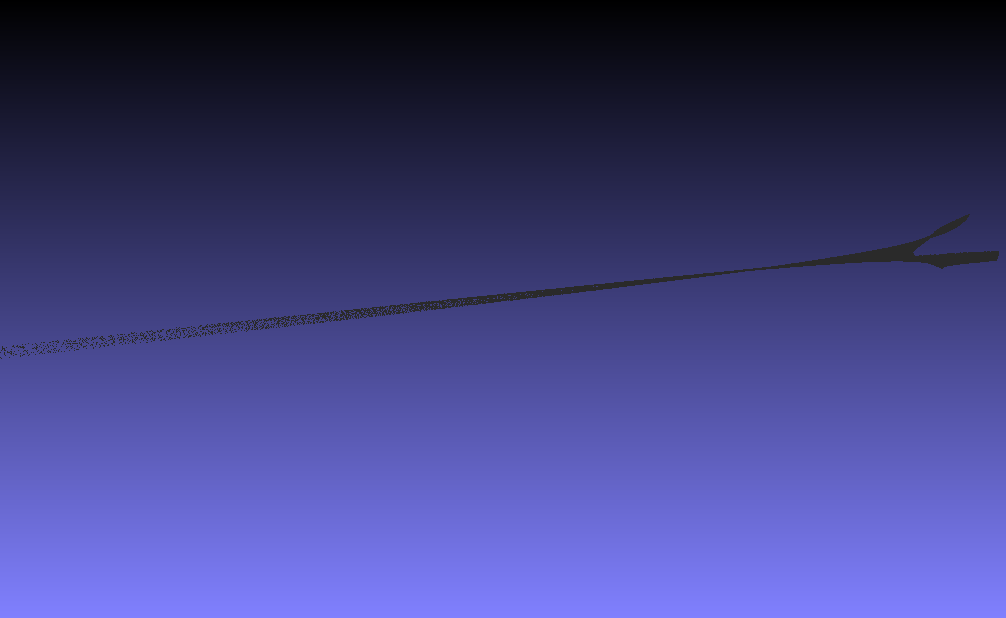
Starting scan 0...
Pattern sequence capture completed in... 2547ms
Images retreived from buffer in... 909ms
Patterns sorted in... 28ms
NOT enough images. Scans may have been too dark. Please rescan.


Waiting for point cloud viewer to close...

I have all the native setup:

PointGrey Grasshopper3 camera

STAR-065 EVM, type s600 by ViALUX (blue LED)

It looks like I'm missing something, but I still wonder what.

Thanks again for reviewing that!

  • Hi Nikolay,

    Welcome to DLP section of TI E2E community. Are you using default configuration or have changed something ?

    -ykc
  • Since you are successfully calibrating, it sounds like the system is working (i.e. the camera is communicating, triggerring, etc. . . ).

    What are you attempting to scan?  This often determines how much light makes it back to the camera.  Very dark objects, very transparent/translucent. or very reflective objects can be challenging.

    A good test would be to choose an object with a fairly Lambertian surface (i.e. like a flat white painted object).  If it does not read that, then there is likely an issue with the pattern projection and image gathering sequence for a real measurement.

    Fizix

  • Hi Fizix!

    Thanks for the reply.

    That’s exactly what I’m doing. I’m taking the checkered board off the screen and trying to scan a flat white surface set to the very same distance as during the calibration process. I tried moving it though, tried various objects, but still no output.

    From what I got out of the manual, I’m supposed to get a flat mesh when I scan a flat non-shiny surface, just a white paper in my case. So far the output is a blank.

    The projector calibration pattern looks fine to me, at least from the visual perception. It’s quite the same as a calibration board, just checkered pattern.

    I thought maybe there’s something wrong with the light capturing process on the camera side since I run a single colour blue LED (that came as a part of the EVM kit). I’ve noticed that the scan patterns are multi-colour, so obviously, the projector misses out on the red and green spectrums of the patterns. But on the other hand, I’m getting pretty good looking output in the calibration subfolder of the application for both the camera and the projector.

    Many thanks for digging into it.
  • Hi, ykc!

    Thanks for the reply.

    I'm running all the standard configuration, I've tried the distribution version of the scanner, tried building the source code with CMake and a DLP-LC SDK. Which I believe is a very same thing. But I had to give it a shot, to shake off the concern.

    I’m about to build a custom application for Altera Cyclone V SoC FPGA, but that's too far away yet. First I'd love to get some output at least.

    Quite puzzled here.

    Thanks again!
  • When it does do a measurement (with the error) how many patterns have you set it up to use and how many does it actually save? If you turn on verbose logging it should show the patterns as it runs by.
  • Thanks, Fixiz!

    I have a default setting of 20 patterns for the camera and ten patterns for the system.

    in "..\bin\calibration\system_images" I have 30 images in total and "DONOTDELETE" file. They are 3 sets with prefixes (system_calibration_capture_camera,
    system_calibration_capture_projector_camera_combo,
    system_calibration_capture_projector_pattern).

    in "..\bin\calibration\camera_images" I have 11 images including the calibration board and "DONOTDELETE" file on the top.

    I can upload the content here if it makes any sense.

    Moreover, I'm sorry, but I didn't figure out how to turn the verbose mode on for the application.
  • Hello Nickolay,

    There should be another directory that has the data when you take a measurement. Make sure that the directory it wants to write to has been created and that you have rights to it. The directories you list are for the calibration, not the measurement.

    We have had issues when the user does not have sufficient rights to write to the directory where measurements are supposed to go. It has been a while so please look in the code to see where it wants to put measurement captures.

    Fizix
  • Fizix, thanks again!

    I'm sorry, but could you give me a clue on what stage of the program it does the measurement? I mean calibration or actual scanning? I'm not looking for you to tell me an exact line, god forbid. It's just a huge bunch of code to look through before I can figure what do I have to debug.

    Or maybe there's a detailed reference somewhere not to overly bug you. I'm very new to the whole subject, that's why it's not that clear to me where to look for that nasty bug. I wish there was somewhat a crash-course I could do.

    Cheers!
  • As a follow-up to my previous post.

    Did you mean enabling the Verbose mode for the CMake build? I did so by amending the CMakeLists.txt with

    set(CMAKE_VERBOSE_MAKEFILE ON)

    But still can't figure where I should look

  • Nickolay,

    I do not mean from the calibration process, but when you go to make a measurement that should return a point cloud.  It should store the latest set of captures.  It does overwrite the previous ones when you make a new measurement.

    I know that for the earlier 4500 unit it was under the main directory (whatever your project name is - for example ours was PW2016 demo in my laptop D: drive.):

    The sub-directory is "output" in my example and has two sub-directories -- "scan_images" and "scan_data".  The images directory has the captures done during the latest measurement.

    It should be somewhere similar for the DLPLCR6500 and DLPLCR9000 systems.

    Fizix

  • Hi Fizix!

    Thanks again for your guidance! Here's some update on the matter.

    It definitely has access to the "..\bin\output\scan_images" & "..\bin\output\scan_data"  folders, as I can see a bunch of images there. I tried to run as a user, as an administrator, and through CLion IDE in a debug mode. But it doesn't seem to be the root of the problem.

    The most important thing is it fell further through to sorting and decoding patterns. Then Point Cloud Reconstruction, and it looks like it's almost there, BUT the *_point_cloud.xyz file is EMPTY 0KB. So it still doesn't work even though it recognizes something like an input.

    Here are some weird things I have noticed so far:

    1. Regardless of how I run the code, I mean just running the .exe file from Windows, running as an Administrator, or through the IDE (should be no difference, really, except for the debug mode). The behaviour is very same. Having my camera & projector fixed relatively to each other and the flat matt-white wall afront of them. In some inconsistent and irrational way, it sometimes gets to the point of decoding and reconstruction and sometimes it doesn't, even though nothing at all has changed physically. I mean the camera, the projector and the wall are all exactly at the very same place while getting those different results. And usually when I can with Vertical patterns it tends to give way less empty shots.

    2. When it falls through to decoding and reconstructing it actually gives me the output to the "..\bin\output\scan_images" folder, 36 images named "scan_capture_[X].bmp", but at some point, it writes the images with a solid rectangular pattern projected, all of them except for some dark images at the end. A couple of times it gave me the output with vertical stripes pattern projected on the image.

    3. It NEVER gives any non-empty .xyz point cloud in return regardless of "NOT enough images. Scans may have been too dark. Please rescan." message showing up or running all the way to reconstructing a point cloud.  And the "Point Cloud Viewer" pop-up window is always black.

    It feels like it works sort of wacky, I mean very much inconsistent in many aspects, and I don't even know where to start the debugging process. The code looks sophisticated enough for days of thorough reviewing. Oh, I also forgot to mention that I have tried installing the distribution version of TIDA-00362_LCr6500_MachineVision on a different machine with the same outcome.

    I wonder if anybody came across such a weird behaviour. Maybe I got a faulty hardware or something is missing on a software side.

    Thanks for your time and patience!

  • Nikolay,

    How are you syncronizing the camera to the projected patterns?

    Fizix
  • Fizix,

    On the software side, I have no Idea how the camera is synchronized with the projected patterns I never made it that far with the TIDA-00362 sample project. All the functionality of the code is intact.

    On the hardware side, it is that cable from the user manual.

    It looks ok on the syncing side, as soon as it calibrates the system and records all the necessary calibration patterns. I mean the calibration could be barely possible if something was wrong there.

    Oh, another interesting fact that it gives me a fairly low number when calibrating the camera:

    Reprojection error (closer to zero is better) = 0.477127

    But here's what I get when calibrating the system:

    Projector calibration succeeded with reprojection error (closer to zero is better) = 2.69276
    Saving camera and projector calibration data...
    Calibration data saved.

    At some point, it was giving me some crazy number for the reprojection error, like 165 something.

    Thank you!

  • Nickolay,

    Please look at the imaged in .\calibration\system images\ .  It seems like they are either too dark or to exposed. You should be able to achieve a projector re-projection error under 1.  Often looking at the images will give you an idea of which direction you need to go -- more or less exposure.

    Try opening your camera iris slightly or stopping it down slightly and try your calibration again.  Although the system may "successfully" complete calibration, it does not mean that it is a good calibration.  Alternatively, you can increase or decrease the gain of the camera.

    Best regards,


    Benjamin L. Lee

    Texas Instruments

    Industrial Applications Support

    DLP® Enterprise and Cinema Display

  • This is a sample image from my ..bin\output\scan_images folder it doesn't look under or overexposed.

    Going further, I was able to capture something really weird. I have reduced the Hz rate of the camera down to 14. It still doesn't scan any surface. At the very bottom of the page is the best output I could get from the scanner so far. Maybe it has something to do with the camera settings.

    Thanks again.

  • I would be one happy guy it was just the camera's exposure. Please check the following post..
  • Benjamin, hello once again.

    Just as a follow-up to my previous post.

    I have tried almost everything that could affect the scanning:

    1. Reinstalled FlyCapture2 SDK couple times to rule it out.
    2. Updated firmware to DLPR900PROM-6500-v5.0.0
    3. Recalibrated camera and the system with different positioning, angles, and aperture settings.
    4. Adjusted the framerate of the camera and the patterns exposure and dark times. Pictures on the output are not overexposed and not underexposed; they look clear and crisp.
    5. With reduced to the 14Hz camera frame rate I'm getting a consistent output. Patterns are projected as they should, and all of the pictures are saved to the right place.

    Thus far I'm not getting anything better than the screenshot with a weird tubular-shaped thing from the previous post.

    It's apparently either me doing something wrong or a faulty hardware/software bugs. On a software side, I can't say on the lower DLP_SDK level, but all of the front-end looks fine.

    I'm struggling for many days just to get an output, can I maybe have a brief conversation with a TI Professional to localize the problem.

    As always, I appreciate your time and help very much!
  • Hi Nikolay,

    Just to let you know Benjamin has gone on vacation. I will try to help you. First make sure projection images are good. Just try the EVM alone with GUI and try displaying some patterns.
    If that is fine, then camera is synchronised with trigger signals to EVM controller board J20 . You can look at these signals if these are properly sent to controller board. Each trigger pulse will cause a pattern to be displayed.

    -ykc
  • Hi, ykc!

    I appreciate your help very much. Thus far as I have previously mentioned, I have all the hardware working correctly.

    Camera triggers projector, and I'm getting all the scan images, including calibration and scanning. I can upload a zip file with the output I'm getting.

    To some unknown reason, it never reconstructs a point cloud, no matter what I do. It is a consistent issue that persists on multiple machines and OS's. I have just reinstalled everything from scratch under windows7, but I get EXACTLY the same outcome.

    I'm trying to establish whether it is a hardware failure or it's me making the same mistake over and over under various platforms and builds.

    I'm very much confused here; I'm afraid there's none out there to help except for you guys.

    Thanks again!

  • Hi Nikolay,

    Please see on scope - trigger in (J20) and trigger out (J24)signals. And check these are synchronised. Also you can try changing trigger in delay in GUI->Pattern Settings page in case these are not synchronised. Camera needs to take shot when pattern is displayed if not synchronised then it will capture wrongly.

    Try checking camera standalone.

    -ykc
  • Hi, ykc!

    I don't Have an oscilloscope here, unfortunately, but isn't the fact that that the system outputs clean and clear images into ..\bin\output\scan_images at a different framerates during the scanning process a sign of a proper triggering? On the top I have no flickering during calibration process at 150Hz frame rate for the camera and 10000/10000 us light/dark time setting for the projector. As a reverse logic I have tried altering the delay time and an impulse time on the camera’s output through the FlyCapture2 dashboard, and when I tweak it on a high frame rate, the image starts to flicker during the calibration.

    I mean I can check the impulse timing of J24 relatively to the input on J20 with a scope, but it doesn't seem to be a root of the problem. I do believe it should have given me some choppy point cloud or at least something like an output even in case there was a minor synchronization offset, again as far as I get a good looking output in the scan_images folder.

    Thanks again!
  • Hello Nickolay,

    I am on vacation, but checking the forums every other day or so.

    I have to say your scan image looks pretty good. What is the camera and projector " reprojection error" on your latest runs.

    Can you capture a screenshot of the steps as you go through calibration and a scan. Also, I assume that you do not have the FlyCapture 2 preview image up while scanning. it should let the capture program have control.

    Fizix
  • Hi Nikolay,

    Can you run LCR6500 evm in video mode(fixed solid color) and let trigger in come(it will be ignored) and see captured images by camera. Do they still show weird captures?

    -ykc
  • Hi, Fizix!

    Thank you very much for your efforts on this one, especially during the Christmas time!

    For sure I never run FlyCapture2 dashboard in parallel with TIDA-00362 scanner build.

    I'll recalibrate the system once again making screenshots while calibrating both camera and the system, describing my steps. I hope we are almost there!

    Nik.
  • Hi, FIzix!

    Please find all the details of the system setup and calibration in the attached pdf!

    Thanks again!

    Steps I make setting up and calibrating the system.pdf

  • Nikolay,

    Thank you for the detailed steps!! These look fairly good, but on both calibration sets try having some images with the board tilted left / right and tipped up / down also. See if this improves your "re-projection error".

    It have been a long time since I have run this demo and software, but some of it is coming back. I will continue to contemplate what may be wrong. I cant think of anything at this moment.

    Fizix
  • Hi Fizix!

    I did. I have tried reducing the camera's FOV eliminating a majority of the dark area. I've tilted, angled, perspective wrapped the board, during the calibration. As well as detached the camera from the system and calibrated it separately from the projector. Everything.

    At the point, the hardware performs flawlessly. I have replaced the test bench computer with a high-performance machine. Even at framerates over 200Hz, I get very crisp pictures with the patterns superimposed every time.

    There must be some logical breakdown. I mean either I'm missing something in the geometry setup and calibration, or there's just a bug in the code. But from what I understood it should genuinely work as-is without any tweaks, which is to my great misluck not happening.

    Maybe there is anyone out there who is familiar with the logical backend of the application to troubleshoot.  I would very much appreciate that kind of a reference.

    I mean even having 2+ reprojection error may drop the accuracy while shouldn't be a reason for an empty cloud output especially after rebuilding the application under Win7, Win10 and endless ways of calibrating, recalibrating etc.. and still the same outcome.

    Merry Christmas and a Happy new year!

    All the best, Nik.

  • Nikolay,

    Are you running from the pre-compiled version or did you compile your own?  This sounds like there is some module incorrectly selected during the point cloud generation portion of the measurement process.

    I will be back in the office toward the later part of next week.  I am having a hard time wrapping my brain around what could be going wrong.

    If you are compiling the code and running it, then try putting in some "I am here - <step location in code>" to see if you are getting to all the places you expect.

    Fizix