This thread has been locked.

If you have a related question, please click the "Ask a related question" button in the top right corner. The newly created question will be automatically linked to this question.

DLPA2000: Reducing VLED Buck-Boost Input Current Spikes

Part Number: DLPA2000

Hello,

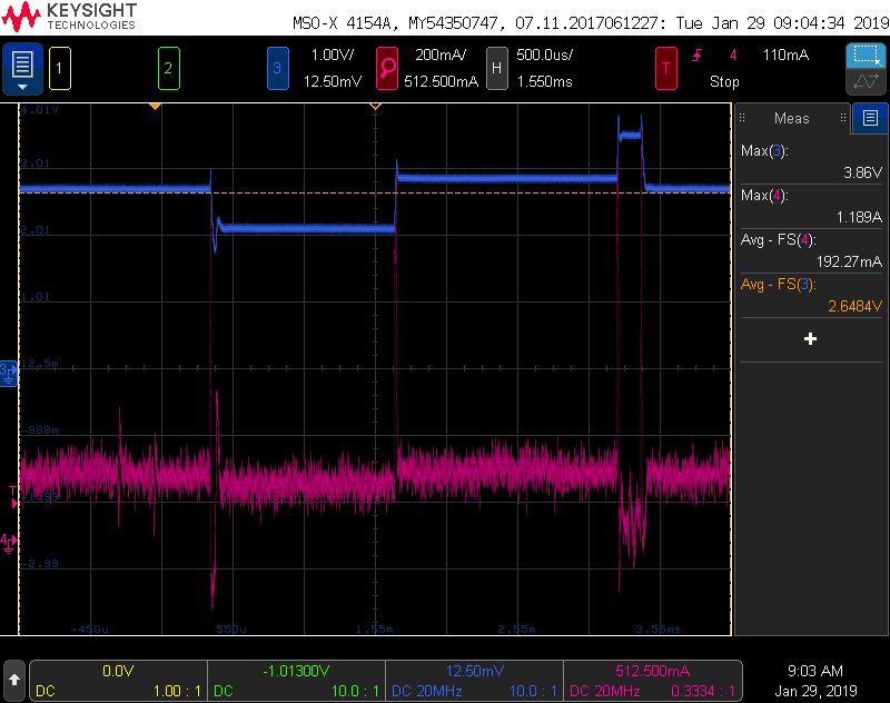
The maximum LED current we are aiming for is only ~300mA.  However, transitioning between Red, Green, and Blue, there are huge input current spikes (1.5A) since the buck-boost is trying to fill the output capacitors as fast as possible.  I am worried these current spikes will result in voltage dips throughout the entire VSYS rail that will cause buzzing caps.  

Since the target current is much lower than the chip's max current (750mA), is there any way to reduce the input current spikes?   

Could we reduce the VLED capacitance since our max loading current is lower than normal?  

Are there any internal registers that would slow down the VLED voltage ramps?  

Thanks,
G

  • Hello Gerald,

    Are you able to share the waveforms you are describing along with your schematic concerning this part of the circuit?

    Thanks,
    Kyle
  • Below is a screenshot of the input current waveform for the entire PMIC.  This is sensed across a 10mOhms resistor with a differential probe.  Is this magnitude current spike expected?

  • Hi Gerald,

    I would generally not expect that high of a current spike. Are you able to share your schematic showing your input capacitance and the DLPA2000 circuit? It would also be helpful to see Vled along with IVled (if possible).

    Thanks,
    Kyle
  • Below is a section of our schematic specific to the VLED buck boost.

    Note that 2 of the PPVLED capacitors are not placed.  The total output capacitance is ~44uF for the waveform i presented.  I will provide a combined V and I waveform shortly.  

  • CH3: VLED CH4 ILED (anode):

    CH3: VLED CH4: I_Input

  • Hi Gerald,

    Thanks for uploading the waveforms. Let me discuss with a coworker of some possible ideas and I'll get back to you as soon as I can.

    Thanks,
    Kyle
  • Hi Gerald,

    After discussing, there are a few possibilities to look at. First, I would like to confirm one would expect some amount of current spikes on the input when switching from a lower LED voltage to a higher LED voltage. This is because the capacitors on Vled will need to charge to the new, higher voltage. These capacitors will provide a low impedance path to ground as they are charged, thus the current spike.

    In order to further reduce the spike I would recommend even further reducing the Vled capacitance. As long as your voltage is stable, you can experimentally continue to decrease capacitance until the input current spikes are decreased. Additionally, feel free to add additional capacitance to the input voltage to ensure even better stability to provide the needed instantaneous current. I would also like to confirm you are only populating one of your inductors.

    Lastly, you may want to consider further increasing Rlim to further increase your signal to noise ratio. You can do this since you do not need the full maximum current the DLPA2000 is capable of outputting.

    Thanks,
    Kyle
  • Thanks. Yes, only 1 of the inductors is placed.

    If we decided to reduce capacitance, is there a particular indicator that is recommended? I'm thinking that i will measure overshoot during the voltage step and make sure it is not underdamped (i.e. no noticeable swinging before steady state is reached).

    Once we lock down on max current, I will increase RLIM accordingly to improve signal.

    Thanks,
    Gerald
  • Hi Gerald,

    I would recommend initially keeping the 2.2uH. If we see other issues after fixing the current issue we can look at increasing the inductor.

    Thanks,
    Kyle