This thread has been locked.

If you have a related question, please click the "Ask a related question" button in the top right corner. The newly created question will be automatically linked to this question.

DLPC3433: DLPC3433 Does not boot

Part Number: DLPC3433
Other Parts Discussed in Thread: DLPA2000, , DLP3010

We have a custom board with the DLPC3433 and the DLPA2000. Currently we are bringing up the board but it doesn't boot.

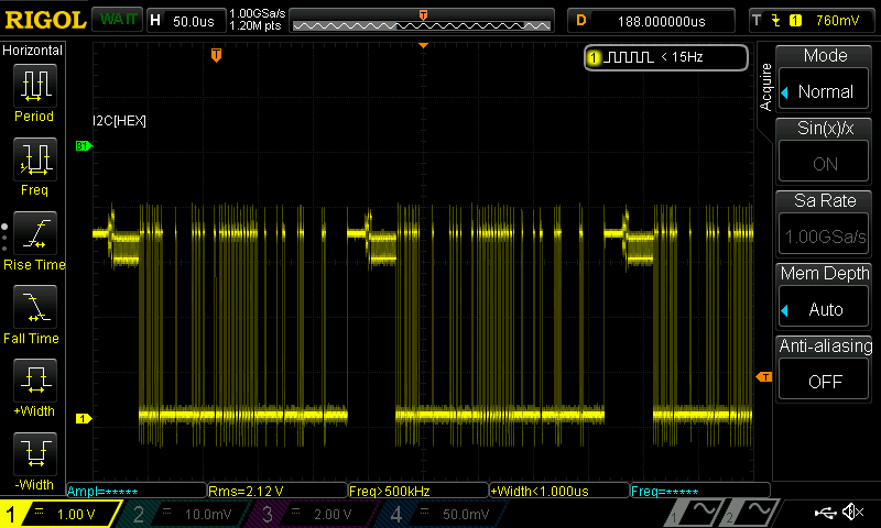
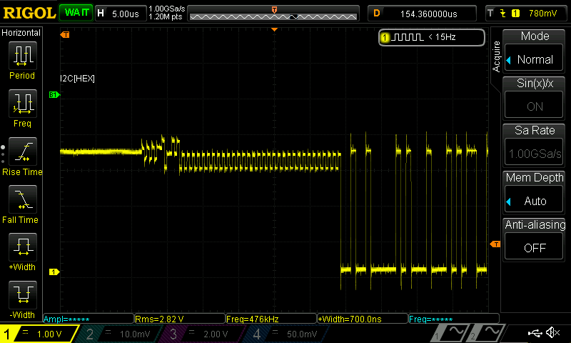
We see strange signals on the Data output of the Flash. See the images. The used flash chip is a MX25R1635FZUIH0.

All voltages seem to be okay.

Any idea why this is happening?

  • Hello Robin,

    Could you please confirm what firmware you are using? Additionally please confirm the DLP3010 DMD is attached, the 1.1V and 1.8V controller rails are coming up, and the PROJ_ON signal is being applied to boot the device.

    Thanks,

    Kyle 

  • Hi Kyle,

    The DMD is connected.

    We are using the following firmware "FWSel_DLPC3433_DLPA2000_pm2_i2c0x36_v7p4p2.img" 

    The 1.1V and 1.8V rails are coming up. And the PROJ_ON is applied. 

    Best regards

    Robin

  • Hello Robin,

    Are you able to let me know of any discrepancies between your startup waveform and the one shown below:

    Thanks,

    Kyle

  • Hi Kyle,

    It is almost the same, 

    VDDLP12 and VDD are tied together. 

    And VCC_INTF and VCC_FLSH are 3.3 Volt and always enabled.

    I see the 24MHz xtal oscillator working and generating a clean signal.

    Best regards,

    Robin

  • Hi Kyle,

    The schematic

    Best Regards,

    RobinMainPCB.pdf

  • Hello Robin,

    Thanks for providing the schematic. I have a few comments and questions:

    • I noticed you have a 4.7k pull-up resistor for INTZ. You may want to increase this to 10k to ensure the PMIC can properly drive the signal low when needed. 
    • What is the NSRST signal? Is it asserted (goes low) before PROJ_ON is asserted? 
    • Is the DMD attached via a flex cable with appropriate decoupling capacitors?
    • How was the flash programmed? Was it verified to be properly programmed (using some external programming tool)?
    • Does HOST_IRQ ever go low or does it remain high after startup? 

    Thanks,

    Kyle

  • Hi Kyle,

    • We will try to change the resistor, but we see that the RESETZ signal before and after the AND gate is correct.
    • It is an external RESET so that the micro controller can program the FLASH connect via J3 and J1 can program the FLASH
    • Yes, the DMD module has quite a few capacitors
    • We programmed the flash through the micro-controller, which is byte for byte raw copy of the .img file. We did a full readback from that flash
    • HOST_IRQ remains high

    We also see no movement on the low speed interface to the DMD. And we only see that flash interface is doing a FAST READ 0x0B on address 0. And it does keep repeating that command.

    Is there something patricular on how the flash should be written? Big endian vs Little endian,... Now it is just a byte for byte copy

    Best regards,

    Robin

  • Hi Robin,


    So the DLPC3433 seems to only ever try to read a particular byte from the flash and never moves on? Everything you have done seems correct so far. Have you tried with a different flash or different DLPC3433 controller to replicate the problem? 

    Thanks,

    Kyle 

  • Hi Kyle,

    I made some progress, we connected a logic analyzer to the flash and saw that the nibble of each byte were swapped, we fixed that. And now HOST_IRQ goes low, and we have I2C access, but no image. VRST/VOFS and all the other are okay.

    When we read out the status registers of the DLPC3433 we get the following, (I used https://www.ti.com/lit/ug/dlpu020c/dlpu020c.pdf as info)

    0xD0 --> 0x81
    0xD2 --> 0x01 - 0x00 - 0x00 - 0x08
    0xD4 --> 0x01
    0xD5 --> 0x60 - 0x0d - 0x00 - 0x87

    So 0xD2 stells me that something on the DMD side is problematic.

    "The system sets the DMD device error for the following conditions:
    • The system cannot read the DMD device ID from the DMD.
    • The system-specified DMD device ID does not match the actual DMD device ID."

    Then I check 0xD5 and see that the device ID that I read is not the same as mentioned in the document. Which is 60h 0Dh 00h 68h. Because the first byte are correct I don't think it is a communication issue but more a configuration problem? I think that the number in that datasheet is the same as the DLP3010?

    We use the following optical engine/projector: https://enhancedworld.com/wp-content/uploads/2019/11/Tech_Spec_40FOV-Light-Engine.pdf

    Any idea what could be wrong?

    Best regards,

    Robin

  • Hello Robin,

    I'm confused on a few of your readbacks. Command 0xD0 should just return one status byte. And 0xD2 should just be the embedded software version number (which looks okay). The DMD device ID looks acceptable to me as it is merely an updated device number for our newer version of the DLP3010. 

    In either case I am glad you are able to communicate with the device. Usually once we can get to this point it means things are ok. Do you not see the LEDs illuminating or the DMD mirrors flipping?

    Thanks,

    Kyle 

  • Hi Kyle,

    I made a mistake, I was indeed reading 0xD2 whilest I was think it was 0xD1. I changed my software, and have read now D1 which returns 0x00 0x07 0x00 0x00. Which seems okay.

    So the statusses seem good, which already a relief, but image is not there yet. 

    Are there any other test that I can do?

    Best regards,

    Robin

  • Hello Robin,

    Could you clarify what you mean by an image is not there? Are the DMD mirrors flipping? Are the LEDs illuminating? 

    Thanks,

    Kyle

  • Progress!

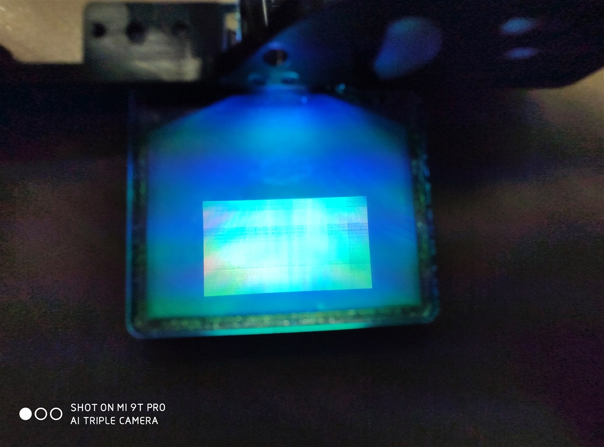
    We had a bad cable. Now I see the leds illuminating. And some "image", see the picture. Change the input to the spash screen doesn't do much. Need to investigate that further. I expected that the image would be fully white.

    Thank a lot!

    Robin

  • Hello Robin,


    I'm glad we are now able to get light output. I would recommend starting with test patterns as they are easiest to debug. Could you also double check that your pin mapping option selected is the same as done in your schematic?


    Thanks,

    Kyle

  • Hi Kyle,

    It works, I can now see the splash screen and other test patterns!

    Thank you a lot!

    How can we change the splash screen?

    Best regards,

    Robin

  • Hello Robin,

    You could try using the EVM GUI; however, unfortunately the GUI may not work to update splash images with non-native EVMs firmware.

    Thanks,

    Kyle