


Other Parts Discussed in Thread: DLP3030-Q1,
The first automotive qualified DMD devices (DLP3030-Q1 and DLP553X-Q1) had pin grid array (PGA) packages that could be directly mounted into a socket component which was soldered to the PCB. However, these PGA packages were large and often more expensive than other options. Some newer automotive qualified packages use a landing grid array (LGA) package that uses an interposer, rather than a socket, to connect the DMD to the PCB. These packages can be made smaller than the PGA packages and are more accurately sized to the 0.3” and 0.55” DMDs, but they are designed to mount the DMD between the PCB and the optical engine. This can present some small challenges when testing just the electronics portion of the automotive projector design before the optical engine has been manufactured. In order develop electronics and optics in parallel, some additional hardware will be required besides the DMD, PCB, and interposer.
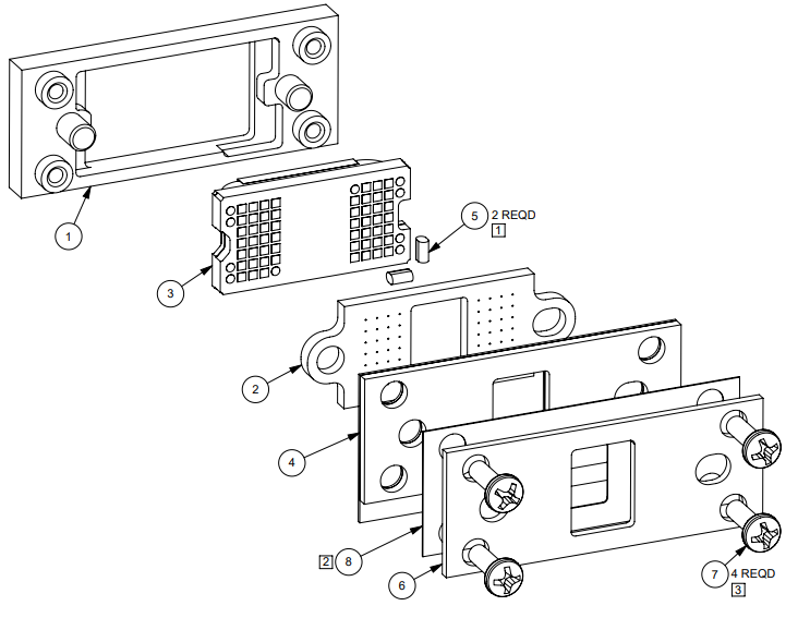
The full design documentation for sample mounting hardware for the DLP3021-Q1 in the s247 LGA package can be found on the product folder page for the DLP3021-Q1 under S247 DMD Mounting and Electrical Interconnect Information. Some or all of these components may need to be purchased or manufactured in order to test PCB electronics with a DMD in an LGA package. Mounting hardware designs for other LGA package DMDs can be found on the respective DMD product folder pages on TI.com.