This thread has been locked.

If you have a related question, please click the "Ask a related question" button in the top right corner. The newly created question will be automatically linked to this question.

DLP4710EVM-LC: External video pattern question

Part Number: DLP4710EVM-LC
Other Parts Discussed in Thread: DLPC3479, DLPC-API

Hi TI,

I have some questions regarding DLP4710EVM-LC, could you please give me a hand?

I want to project a series of 2D images (not vertical or horizontal lines) and want to know my option is with 4710EVM-LC.

(1) Can 4710 EVM-LC store more than 4 splash images (GUI only shows 4 but how many images or size can it store)?

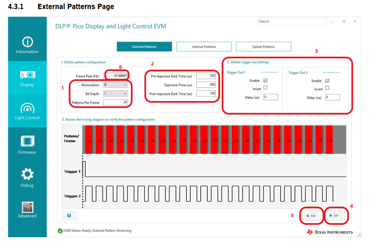
(2) If I project a series of  images (single color, I think I can set bit depth to 1, frame by frame from PC), using external pattern mode (via HDMI). Will projector detect the image (frame) change and set trigger 1 to high at the beginning of each new frame? How many frames can I project in 1s? 

Thanks!

Derlin


  • Derlin,

    The DLPC3479 chipset can store any number of splash screens so long as the flash memory implemented in the system is large enough. In the case of the 4710-LC EVM, however, it is set up to only accept four splash screens. If you were to design a custom board you could use a larger flash memory with more splash screens.

    As for the frame rate, the DLPC3479 chipset supports high-speed pattern rates up to 1440 Hz (1- bit) and 180 Hz (8-bit) in external video mode. This is accomplished by inputting standard 60 Hz frames over the HDMI input with the 24 bits of RGB data packed with encoded patterns. For example, with 8-bit pattern mode you would have each color (R,G,B) present an 8-bit pattern during the 60 Hz frame, which is decoded by the DLPC3479 to result in an effective pattern rate of 180 Hz on the DMD output.

    I hope this helps.

    Regards,

    Philippe Dollo

  • Hi Philippe,

    Thanks for your answer.

    I know the patterns will be fed from HDMI port, however I don't understand how to compress several patterns in one frame? How can projector know when to send out trigger 1 (between frame) or trigger 2 (between pattern) as below.

    We are using OpenCV "imshow", is that correct tool to do it? 

    Thanks!

    Derlin       

  • Hi Derlin,

    Thank you for your patience on the coming support.

    Your inquiry on pattern compression is important to us, but our team will likely be unable to reply until the new year.

    Kind regards,

    Austin

  • Derlin,

    I recommend you start by looking at section 8.3.1.1 of the DLPC3479 datasheet for discussion on this topic:

    https://www.ti.com/lit/ds/symlink/dlpc3479.pdf 

    Next, you should look at our FAQ on Light Control EVMs:

    https://e2e.ti.com/support/dlp/f/94/t/729968

    Each of the 24 bits in an RGB888 video signal in your case are being repurposed to encode/represent the 24 individual patterns being displayed. Instead of displaying each bit for a different amount of time, the DLPC3479 chipset will present each bit as an individual pattern for the set exposure time. By encoding the patterns as individual its (from R[0] to R[8], G[0] to G[8], B[0] to B[8]) it becomes easy to transmit the patterns over a standard HDMI transceiver.

    The DLPC3479 knows the timing it needs to provide for each bit, so it thus knows (based on your GUI configuration) when to issue each trigger out signal.

    Let me know if you want to go into any depth on the above topic. I hope this helps.

    Regards,

    Philippe Dollo

  • Hi Philippe,

    Thanks for your reply.

    I still don't have any clue on how to project external 2-D patterns via HDMI . Do you have an example on how you do it?

    We usually send out pictures to projector using OpenCV imshow() function, but I don't think it is correct. How do you encode 3 patterns in one frame?

    Thanks!

    Derlin     

  • Hello Derlin,

    Thank you for your patience. We will respond to your questions by the end of the week.

    Regards,

    Austin

  • Derlin,

    Having 3 8-bit patterns (or 24 1-bit patterns) per 60 Hz frame is feasible because with a DLP Light Control system, each of the 24 bits are displayed on the DMD as individual bit planes discretely. For example, the entirely of the DMD will at a point in time be displaying the contents of Green Bit 0, and another time will display Red Bit 7.

    In order to send your 8-bit patterns through the HDMI interface (with OpenCV or whatever video source you choose to use) you will essentially be encoding each of the three patterns as one of the three RGB LED colors. You would generate an image with an 8-bit Red pattern, 8-bit Green pattern, and 8-bit Blue pattern within the same image frame and sent it all at once as a single RGB888 24-bit packet to the DLPC3479 system.

    I hope this helps.

    Regards,

    Philippe Dollo

  • Hi Philippe,

    Thank you for your reply, I tried the following code but nothing happen, could you please take a time to look it?

            CY_I2C_CONFIG cyI2CConfig;
            CY_DATA_BUFFER cyDataBuffer;
            CY_I2C_DATA_CONFIG cyI2CDataConfig;
            unsigned char readBuffer[4096], writeBuffer[4096];
          
           // TI projector address

            cyI2CDataConfig.slaveAddress = 0x1B;
          
            memset(writeBuffer, 0x00, 4096);
            cyDataBuffer.buffer = writeBuffer;

            cyDataBuffer.buffer[0] = 0x52;  // LED disable
            cyDataBuffer.buffer[1] = 0x00;  //
        
            cyDataBuffer.length = 2;
        
            rStatus = CyI2cWrite(handle, &cyI2CDataConfig, &cyDataBuffer, timeout);
            
            if (rStatus != CY_SUCCESS)
            {
               printf("LED Diable fail \n");
            }
            sleep(0.5);
           

            // Load image to code   

            cv::Mat test_1 = cv::imread("1.png");
        
            
            memset(writeBuffer, 0x00, 4096);
            cyDataBuffer.buffer = writeBuffer;

            cyDataBuffer.buffer[0] = 0x96;  //   
            cyDataBuffer.buffer[1] = 0x00;  // 1 bit mono
            cyDataBuffer.buffer[2] = 0x01;  // One patten  
            cyDataBuffer.buffer[3] = 0x01;  // Red
            cyDataBuffer.buffer[4] = 0x10;  // Illuminatiom time 1st byte  10ms
            cyDataBuffer.buffer[5] = 0x27;  // Illuminatiom time 2nd byte  
            cyDataBuffer.buffer[6] = 0x00;  // Illuminatiom time 3rd byte   
            cyDataBuffer.buffer[7] = 0x00;  // Illuminatiom time 4th byte
            cyDataBuffer.buffer[8] = 0xB8;  // Pre-Dark 1st byte                 3ms  
            cyDataBuffer.buffer[9] = 0x0B;  // Pre-Dark 2nd byte
            cyDataBuffer.buffer[10] = 0x00; // Pre-Dark 3rd byte   
            cyDataBuffer.buffer[11] = 0x00; // Pre-Dark 4th byte
            cyDataBuffer.buffer[12] = 0x03; // Post-Dark 1st byte               3ms
            cyDataBuffer.buffer[13] = 0x96; // Post-Dark 2nd byte
            cyDataBuffer.buffer[14] = 0x03; // Post-Dark 3rd byte
            cyDataBuffer.buffer[15] = 0x03; // Post-Dark 4th byte
            cyDataBuffer.length = 16;
        
            rStatus = CyI2cWrite(handle, &cyI2CDataConfig, &cyDataBuffer, timeout);
            
            if (rStatus != CY_SUCCESS)
            {
               printf("Write  Fail \n");
            }
            sleep(0.5);

        
             memset(writeBuffer, 0x00, 4096);
            cyDataBuffer.buffer = writeBuffer;

            cyDataBuffer.buffer[0] = 0x05;  // light control-external pattern
            cyDataBuffer.buffer[1] = 0x03;  //
        
            cyDataBuffer.length = 2;
        
            rStatus = CyI2cWrite(handle, &cyI2CDataConfig, &cyDataBuffer, timeout);
            
            if (rStatus != CY_SUCCESS)
            {
               printf("External pattern setting fail \n");
            }
            sleep(0.5);

            memset(writeBuffer, 0x00, 4096);
            cyDataBuffer.buffer = writeBuffer;
            
            cyDataBuffer.buffer[0] = 0x92; // trigger out setting
            cyDataBuffer.buffer[1] = 0x03; // selete trigger 2 (bit0=1)  enable (bit1=1) Not inverted (bit2=0) 00000-011
            cyDataBuffer.buffer[2] = 0x00; // Not delay 4 bytes
            cyDataBuffer.buffer[3] = 0x00;
            cyDataBuffer.buffer[4] = 0x00;
            cyDataBuffer.buffer[5] = 0x00;
           
            cyDataBuffer.length = 6;

            rStatus = CyI2cWrite(handle, &cyI2CDataConfig, &cyDataBuffer, timeout);
                  
            sleep(0.5);


            cyDataBuffer.buffer[0] = 0x52;  // LED Enable
            cyDataBuffer.buffer[1] = 0x07;  //
        
            cyDataBuffer.length = 2;
        
            rStatus = CyI2cWrite(handle, &cyI2CDataConfig, &cyDataBuffer, timeout);
            
            if (rStatus != CY_SUCCESS)
            {
               printf("LED Enable fail \n");
            }
          

             //Project pattern
             cv::imshow("1",test_1);

    The pattern is as below, I tried 1bit mono (on or off) in red. 


    Is there anything I need to add?

    Thanks!

    Derlin

  • Derlin,

    What is the content of the image you are pushing through your OpenCV software? Did you encode your patterns within?

    I can't comment on the OpenCV code itself. You probably will need to consult with available community resources for the OpenCV library for help with syntax and coding.

    As for pseudo code and implementation help, you could try consulting our DLPC-API library (which is C-based) for some reference:

    https://www.ti.com/tool/DLPC-API

    I hope this helps.

    Regards,

    Philippe Dollo

  • Hi Philippe,

    I received your replay (though not shown on this post). Can I ask you more questions? Can png or jpeg picture be used as pattern for external pattern streaming mode?

    What software does TI recommend  to use for external pattern?

    Thanks!

    Derlin

  • Hi Derlin,

    Our team will respond by the end of the day on Friday (1/15). Thank you for your patience.

    Regards,

    Austin

  • Hi Philippe,

    I use GUI to setup external pattern stream mode (RGB, 8bit 3 pattern, trigger2 out), and I can see the trigger2 out signals when HDMI port is connected to PC.

    I think I understand how to encod the patterns now.

    My new question is the projector keep sending out trigger signals when HDMI is connected to PC. There is no way for me to sync trigger 2 signal of each pattern with camera.

    Any suggestion?

    Thanks!

    Derlin     


  • Derlin,

    Thank you for your patience. We will be back to you by EOD 1/15.

    Regards,

    Austin

  • Derlin,

    Are you trying to set up the input triggers for the camera?

    If you are doing internal pattern streaming, you can just use the TRIG_IN signal for this purpose (per the DLPC3479 datasheet). This trigger is not available when using external pattern streaming mode.

    The output triggers are active during each frame signal, they would be controlled by the VSYNC of the video stream in this case.

    Regards,

    Philippe Dollo