This thread has been locked.

If you have a related question, please click the "Ask a related question" button in the top right corner. The newly created question will be automatically linked to this question.

DLPDLCR4710EVM-G2: EVM Status Connected, turned off

Part Number: DLPDLCR4710EVM-G2
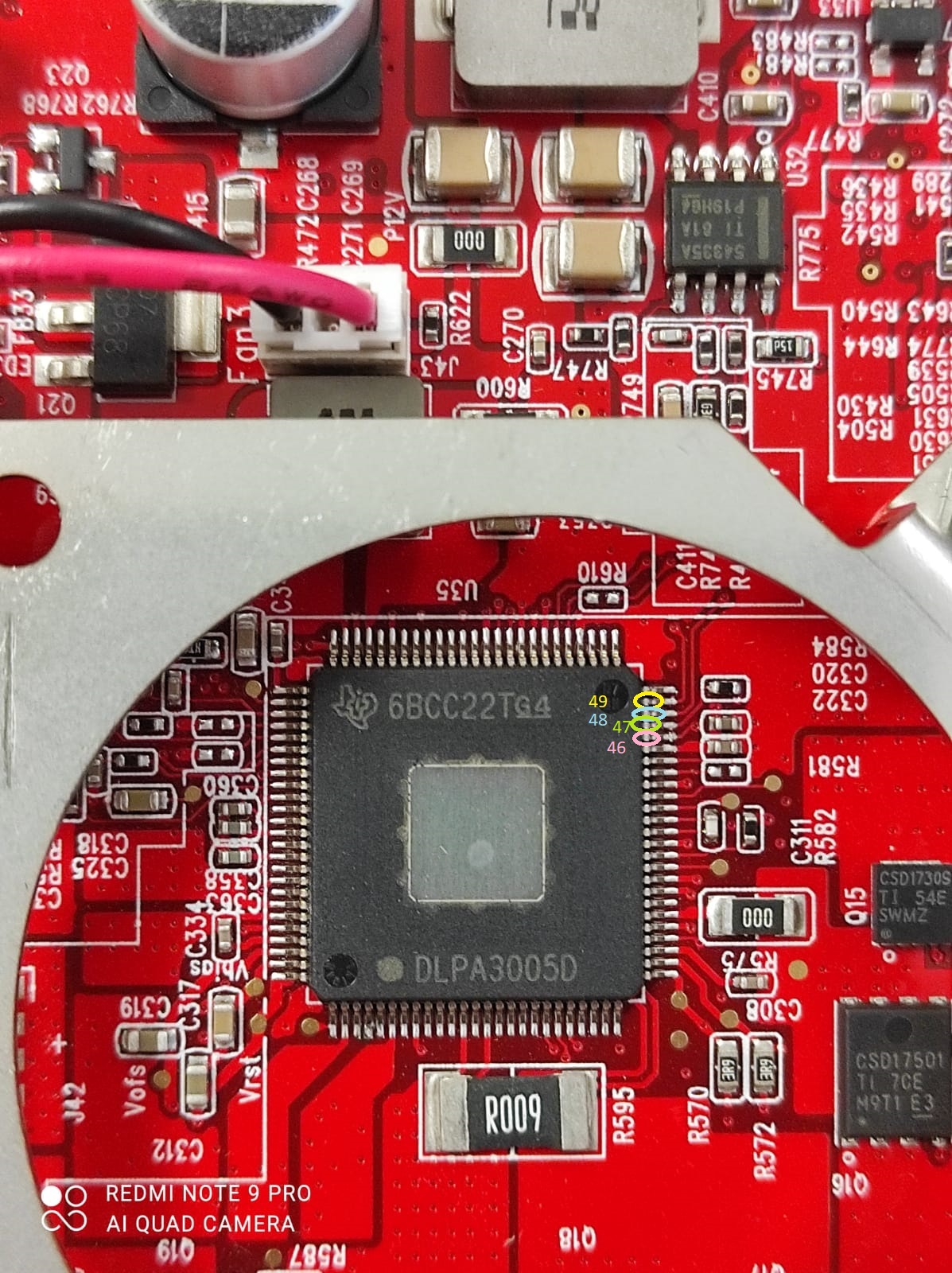
Other Parts Discussed in Thread: DLPC3439, DLPA3005

Hi,


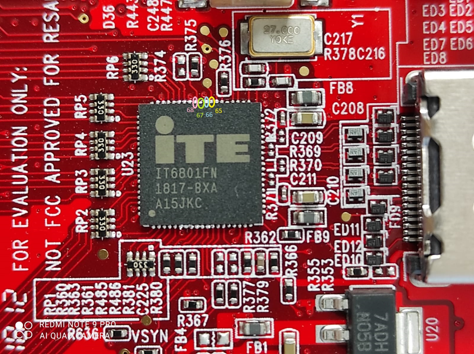
I have received a DLPDLCR4710EVM-G2 device recently. When I installed it and tested it, it worked perfectly fine for some time (let’s say one hour). Then I turned it off, waited for some time (a few minutes) and turned it on again. The fan stared turning normally but there were no images displayed when I pushed the ON/OFF SW_21 switch button. When I use the “DLP Light Crafter Display”, I can get the DMD Information (DLP4710-G2, .47 1080p), but there is nothing in the “Controller” and subsequent text boxes.

Could you help me find a solution to make this device work again?


Best regards,

Bertrand.


  • Bertrand,

    Welcome to the E2E forums, and thank you for your interest in our DLP technology.

    When you can receive some (but not all) of the chipset metadata in the manner you are describing it typically suggests that the DLPC3439 (controller) is not completing boot, but you are still able to communicate with the Cypress USB host on the system. 

    Are you able to issue any I2C commands (following pages)? If not, then the DLPC3439 may need its flash EEPROM to be reprogrammed. You can download a copy of the flash image for this EVM from the respective tool folder:

    https://www.ti.com/tool/DLPDLCR4710EVM-G2

    User's Guide for the GUI: https://www.ti.com/lit/ug/dlpu021b/dlpu021b.pdf 

    I hope this helps.

    Regards,

    Philippe Dollo

  • Thank you for your response. I cannot send any command from the GUI in the different menus.

    I could launch the Firmware update from the "Firmware" menu. I launched it using the "img" file I got following the link you gave me.

    I get an error at the end of the 3/3 step. It says :

    Command "doupdate_full": Bad expression: WriteGPIO(0x24100,0x24100) WriteGPIO: failed

    Then nothing changed : I still cannot have any image displayed by the projector.

    What can I do now?

  • Bertrand,

    Thanks for the update.

    It sounds like the firmware update failed in the "verify" phase. Is that correct? If so, you may want to check whether the SPI lines on the EEPROM are working. The EEPROM flash device on the EVM is where the image file is stored.

    Using a scope, you could probe the MISO and MOSI lines (and clock) to see whether there is any activity coming out of the device. If you need help finding the EEPROM you can check the schematic or layout of the reference design here:

    https://www.ti.com/tool/TIDA-01226 

    Regards,

    Philippe Dollo

  • Thank you Philippe for your response.

    I also think that the firmware update failed during the last verification phase. I will check the MISO and MOSI lines and clock tomorrow since I am not in the lab for the moment.

    Could you please confirm that the signals you want me to check should be measured on pins 46, 47 and 49 of the DLPA3005?

    Could you also tell ma what you suspect as the cause of this problem?

    Best regards,

    Bertrand Wattrisse.

  • Hello Bertrand,

    Yes, these are the pins you will want to probe. You may also consider probing test points 65, 66, 67, and 68 on the EVM. Please try probing these when the board is powered during the boot process.

    Regards,

    Austin

  • Hello,


    We have checked the signals on the test points and we had the following responses (they were identical in the boot process and in the "steady state") :

    A) IT6801 component

    - test point 65: periodic signal from 0V to 3.3 V at around 3 MHz. The shape of the signal is a kind of "damped square".

    - test point 66: continuous 3.3V

    - test point 67: continuous 1V

    - test point 68: continuous 0V


    B) DLPA3005 component

    - test point 46: continuous 0V

    - test point 47: continuous 0V

    - test point 48: continuous 0V

    - test point 49: continuous 0V


    Here is the photo of the IT6801 component showing the location of the test points:


    Here is the photo of the DLPA3005 component showing the location of the test points:


    It seems that the DLPA3005 is not working properly. I think that you should now consider to exchange my DLPDLCR4710EVM-G2 that should still be under warranty.


    Best regards,

    Bertrand Wattrisse.


  • Bertrand,

    Did you check these signals with a multimeter or oscilloscope? The PMIC points tested correspond to the MOSI/MISO lines (which may not be detectable by the multimeter).

    Moreover, I was particularly specifiying you check the MOSI/MISO lines on the EEPROM device to see if there was any communication between the EEPROM and the DLPC3439. This device can be found as U18 in the EVM schematic, which you can download here:

    https://www.ti.com/tool/TIDA-01226

    This EEPROM device is the one that the system is actually attempting to write to when the "Verify Failed" error occurs. 

    I hope this clears up any confusion.

    Regards,

    Philippe Dollo

  • Bertrand,

    Also, per your question above. you can inquire about your warranty/replacement options with TI store support:

    https://www.ti.com/info/contact-us.html

    Look for the TI store support contact information on this page.

    Regards,

    Philippe Dollo

  • Philippe,

    Yes, as suggested, we’ve checked the signals with an oscilloscope. I don’t know how we could have observed the temporal shape of the signal with a multimeter …


    You confirmed to me I should check “pins 46, 47 and 49 of the DLPA3005” and you asked me to check “test points 65, 66, 67, and 68 on the EVM”. The component U18 was never mentioned in any of the mails we exchanged and the pins of this component are labeled from 1 to 8. There are plenty of components on this board, and I think you will understand that is not reasonable for us to check them all one by one. Could you please tell me if you plan other checks? If so, I would appreciate to have the list once and for all. Due to the sanitary situation, we are teleworking and we are not at the lab every day so I fear that this kind of “incremental approach” will be far too long.


    Furthermore, before checking this component, could you please tell me if the responses we got from components IT6801 and DLPA3005 are normal?


    Best regards,

    Bertrand.


  • OK, thank you for the information. I will check the procedure.

    Best regards,

    Bertrand.

  • Bertrand,

    I understand. Apologies for any confusion on the same.

    The behavior you are reporting out implies that the system isn't getting into a boot state where it ever needs to communicate with the DLPA device. This is evidenced by your tests on pins 46-49. These SPI lines are used by the DLPC when communicating with the DLPA during bootup to initialize LED and power settings.  Since you are not seeing any activity then that means the DLPC is never executing the boot sequence where it would configure the DLPA in the first place.

    Since the boot sequence is not occurring and attempting to reprogram the EEPROM results in a verification failure, the most likely possibilities are as follows:

    > The DLPC or the EEPROM device (U18) holding the DLPC object code/image are somehow damaged or faulty such that it is inoperable

    > The board is damaged such that critical communication lanes (SPI communication with the EEPROM, or SPI communication with the DLPA) are cut in some manner

    In either case, there is sufficient cause that I would recommend you contact the TI.com support page mentioned above to ask for a replacement unit.

    I hope this helps. Let me know if you have any additional questions

    Regards,

    Philippe Dollo