This thread has been locked.

If you have a related question, please click the "Ask a related question" button in the top right corner. The newly created question will be automatically linked to this question.

Some question about phase shift algorithm

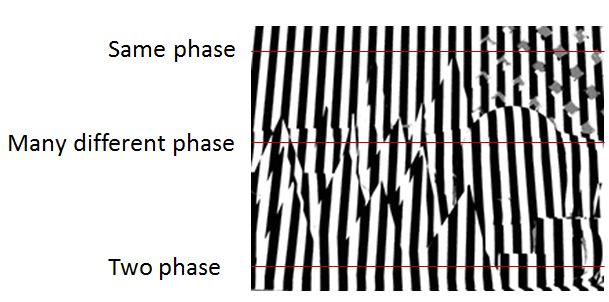
I need to decode the stripe pattern but there is some question.

How to describe the stripe pattern using phase shift equation?

How to define the phase of the stripe pattern?

thanks.

Best regards,Timon

  • Hello Timon,

    Welcome to the DLP section of the TI-E2E community.

    It appears you are referring to grayscale stripe structured light patterns.  Is this correct? 

    If so, then this means that your grayscale value varies spatially as a periodic function of x where x is related to a horizontal (or y = vertical displacement).  The pattern can then be shifted horizontally (or vertically) by adding a constant to x (customarily 180°, 120°, or 90°) where 360° represents one full period of the periodic pattern.

    Often the periodic function is just sin(omega·x) where omega is the period in 2·π·pixels and x is the pixel value in the dimension of interest.

    I hope this helps.

    Fizix.


  • So that means if I use 10th grayscale stripe. I need to define 10 sine wave and phase shift equation? There are different period with different gray code stripe.

    If so, the sine waves are defined on reference stripe in every row (if I use vertical pattern), and to compute the deformation on every sine wave?(deformation means the stripe displacement, or the shifted horizontally)

    And if that is ture, the sine wave of rows may have many phase (because there are many depth in a row), show on the figure.And how can I define the sine wave with many different phase?

    My algorithm will refer to the TI demo system. Have you use three stripe with different phase on the same gray code sequence on the demo system?

    And have you use phase shift sequence combined with gray code sequence?

    thanks for your answer

    Best regards,Timon

  • Timon,

    I think there is some confusion about when you apply the phase shift. Generally you project a periodic pattern with several phase shifts.  This is on the projection side.

    So let's say you sent out sin(omega·x) such that the field of view has 25 stripes.  Then you choose 120° as your shift.  You will then project two more patterns, sin(omega·x + 120°) and sin(omega·x + 240°).  Then you collect the images (similar to above) and use the information to determine depth.  The patterns projected will have the same period (i.e number of stripes), but will be shifted by 1/3 and 2/3 of a period when projected.

    The algorithm to recover the depth information is another matter.  You will have to read articles on how that alogrithm works.  A web search will return a plethora of links that you can read on this subject.  It is the comparison of the expected phase from a flat reference surface and what you actually receive back that determines the depth at that point (x,y) in the field of view.

    Fizix

  • Hello! Fizix,

    Now I concept every gray code stripe need three phase shift the least to compute the phase(also in your algorithm).

    If that is true, the camera needs to capture 32 image when I use 10 gray code level. (all black pattern, all white pattern,and 30 pattern image that involve 10 gray code pattern with 3 different phase)

    But when I capture the LightCrafter projector image, they do not have three phase pattern in capture image.(I think the system needs three phase pattern information on objects,so the camera needs to cpature three phase pattern image every gray code)

    I have to confirm how many gray code pattern is used. The pattern count set "22". (all black pattern, all white pattern, 10 gray code levels, 10 binary code levels or not)

    Why do not have phase shift pattern? (In theory we need to capture 62 image, and actually we only capture 15 images in system include all black and all white pattern)

    thanks for your answers.

    Best Regards,Timon

  • Hello Timon,

    Are you referencing a particular pattern or algorithm?  You refer to 22 patterns.  This sounds like a binary pattern sequence and their inverse patterns using an XGA DMD.  In that case you have 210 = 1024 horizontal bits, therefore 10 patterns & inverses with an all on and all off reference added = 22.  There is no phase involved in this method.

    Could you describe the source of information that you are referencing (i.e. a paper or demonstration given)?  This will help me understand your inquiry.  Thanks.

    Best regards,

    Fizix

  • Hello! Fizix

    I don't know how to define the "particular". However,my acknowledge that we need the phase shift algorithm to discriminate the stripe deformation.

    The pattern and algorithm base on the LightCrafter system which looks like gray code pattern sequence and their inverse pattern.  

    I can understand the inverse pattern can define the shadow region. But if there are no phase shift stripe pattern. How can I get the phase information and to compute the stripe deformation.

    I try to understand the algorithm with LightCrafter demo system. How is the algorithm work? So my reference paper may be not the same method.(my reference paper all used phase shift method,but the demo sytem looks not)

    The system developer is Sanjeev.

    May I have to build a new question because the problem with the wrong tag if the algorithm don't use the phase shift algorithm.

    thanks for your answers

    Best Regards,

    Timon


  • Hello Timon,

    I am not sure how much below explanation helps to all the forum users.

    For those who have seen DLP LightCrafter based 3D Capture demo in trade shows or tech day events. The algorithm used in the demo is discussed in DLPA026 Appnote the link to the document is here http://www.ti.com/lit/an/dlpa026/dlpa026.pdf. Note when this appnote was written we referred to DLP LightCommander Kit but it is applicable for DLP LightCrafter kit also.

    Regards,

    Sanjeev

  • Hello Sanjeev,

    I have ever read the document before. But there are no detail information and explanation on decoding.

    The "decimal matrix" looks like encoding matrix. Every value is a  unique code. And subtract from reference.

    I can't imagine the relationship between the unique code and disparity. Is that means the large different value represent the large disparity? Or I have to find the same unique code in the reference matrix and decimal matrix. And compute the displacement between their position?

    Best Regards,

    Timon


  • Hello Timon,

    In this particular demo the result after subtraction represent the final disparity from the reference. It is a quantitative number, the larger the difference value the larger is the disparity.

    Or I have to find the same unique code in the reference matrix and decimal matrix. And compute the displacement between their position?

    [Sanjeev] You don't need to look for same unique code in the reference matrix and decimal matrix. As I explained above the result matrix after subtraction b/w reference matrix and decimal matrix is the final.

    Regards,

    Sanjeev