This thread has been locked.

If you have a related question, please click the "Ask a related question" button in the top right corner. The newly created question will be automatically linked to this question.

DLPLCR4500EVM: Input Trigger Connector Pins With Arduino

Part Number: DLPLCR4500EVM

Hello,

I have some difficulties controlling the DMD in sequence mode using the Input Trigger Connector Pins.
I'm using an arduino to trigger the DMD: my goal is to activate a pattern when the arduino pin is ON, and turn the pattern off when the pin is OFF.

I set the DMD to pattern sequence mode, with one pattern loaded, triggered by the internal trigger.
I checked that J10 and J12 Voltage Jumpers are set for the 3.3V
I connect my arduino 3.3V pin with a transistor controlled by a digital pin, as follow:

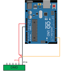
But it doesn't seems to work, it result in LED flickering...

I also tried to connect directly an arduino digital pin (5V) to the J11.5 pin an this seems to work. But I have another problem: when I turn OFF the DMD, it turn off fine, but after ~10-30min the DMD goes ON again...

I think I miss something, notably the J11.4 pin which is called "Trigger In 2 supply". Should I connect this pin directly to the 3.3V ?
Don't you have any idea of what could be the problem ?

Thank you in advance for your help
Matthias

  • Hello Matthias,

    Welcome to the E2E forum and thank you for your interest in DLP technology!

    Try connecting the supply directly to the 3.3V. The transistor implementation may be giving you problems. You may also consider using a voltage divider from a GPIO pin to drive the trigger in place of the transistor. This would ensure that you are controlling the pin with the correct voltage. If you wish to keep the transistor, probe the voltage at the supply and trigger pins.

    I cannot explain why your DMD would power on after 10 - 30 minutes. Probing the supply and trigger lines with an oscilloscope may provide some insight into why this is occurring.

    Please let us know if we can be of further assistance.

    Regards,

    Austin

  • Your solution seems to work thanks. There are still some weird "instabilities" but much less frequent.
    What I understand is that the DMD measure the voltage difference between J11.6 and J11.5, and between J11.6 and J11.4. Then it compare the two value to determine if it's ON or OFF. Is this right ?


    Thanks again
    Regards,
    Matthias

  • Matthias,

    J11.4 is used as the input to Vcca of the voltage translator. I recommend reviewing the schematic associated with the EVM reference design here for more information.

    https://www.ti.com/tool/DLP4500-C350REF

    I hope this helps.

    Best Regards,

    Philippe Dollo

  • Thanks for the information, but these diagrams are too complicated for my skills in electronic.

    I was just trying to understand the general idea of what is happening and why this need 3pins to work.

    In the manual, there are almost no information on how to properly connect the input trigger pins, so any non-expert can be quite lost with this... But thankfully this forum compensate quite nicely.

    Thanks,

    Matthias

  • Matthias,

    The Vcca is used as a reference for the voltage translator. So, you will want it to match closely with the output high value of the input. Let me know where you would like me to elaborate further.

    Regards,

    Philippe