This thread has been locked.

If you have a related question, please click the "Ask a related question" button in the top right corner. The newly created question will be automatically linked to this question.

Getting started programming DLP LightCrafter

Other Parts Discussed in Thread: DLPC300

Hi,

I am trying to figure out how to use the DLP LightCrafter.

I would like to be able to program my own pattern and have the LightCrafter display it. Is this possible and are there sample codes that I can look at for an example?

Any help is appreciated.

Thank you,

Heather

  • HI,

    I updated my software and I am trying to load my own pattern into the LightCrafter. It is still giving me an Error Message (Command Failed) when I ty to set the Pattern Sequence Settings. I was able to update all of the new versions except for the DM365, which might be the problem seeing as though I don't have an SD card. The image/pixel size dimension are correct, but I also cannot upload the Load Pattern Images.

    Any help is appreciated.

    Thank you.

  • Hello Heather,

    Welcome to TI DLP E2E community!

    I can definitely help you get started with Lightcrafter's pattern sequence mode.

    Before you start playing with the LightCrafter GUI, make sure you have downloaded LightCrfater Software bundle 3.0 and updated the DM365 firmware by creating an SD card with the latest DM365 firmware and following the instructions in Users guide to update the firmware from SD card/NAND.

    The following are the detailed steps to upgrade the DM365 firmware on Lightcrafter:

     There are 2 ways to upgrade the DM365 firmware and bootr up the LightCrafter:

    1. Directly from the SD card in which case you build an SD card with lcr_dm365_v5_sd.dat and the switch remains on the side closer to SD card all the time.
    2. Booting it from NAND in which case you build the SD card with lcr_dm365_v5_nand.dat and wait till it gets copied into NAND after which the switch needs to be flipped away from SD card and SD card can be removed.

    These are the detailed steps for the above mentioned methods:

    Steps to follow to boot it up from SD card:

    •             Format the SD Card (The SD card I used is Transcend 4GB micro SD HC).

    •             Run this command on the Command prompt (opened with administrator permissions)

    •        Navigate to the directory “SD Card Utility” inside the downloaded 3.0 Bundle that has .dat file

    o             lcr_boot_sd.exe dm3xx_sd.dat  F:  (or whatever SD card drive is mounted) 

    •             Make sure it comes back and says , Image successfully copied.

    •             Remove the SD card and put it inside the SD card slot on lightcrafter, flip the switch towards the SD card and power it up

    •             You should see a series of images/ splash screens like the one attached

    •             You should not need to flip the switch to the other side in this process.

    •             Note that now onwards, you will always need the SD card inserted in LighTcrafter and the switch always towards the SD card.

    •             Eventually the LightCrafter should boot up completely and you should see the RGB bars and the LED D1 should be blinking Red and green continuously.

    •        After this step, you should be able to connect to it from the GUI (download the latest form LightCrafter 3.0 Software and Firmware Bundle)


    Steps to follow to boot it up from NAND:

    •             Format the SD card

    •             Run the command  lcr_boot_sd.exe dm3xx_NAND.dat  F:  (or whatever SD card drive is mounted)

    •             Now insert the SD card into the SD card slot, make sure the switch is towards the SD card

    •             Power up the Lightcrafter, again watch series of the splash images and watch the LED D1.

    •             As soon as the LED D1 turns green, then flip the switch away from SD card and power the Lightcrafter down and power it back.

    •             Now what it means is, it has copied the firmware over to NAND flash part on the board. Now you can even remove the SD card and it should boot up from NAND.

    •             Note that, now onwards the switch always needs to be in a position away from SD card.

    If you follow these steps, it should be pretty straight forward to upgrade the firmware and boot up the LightCrafter.

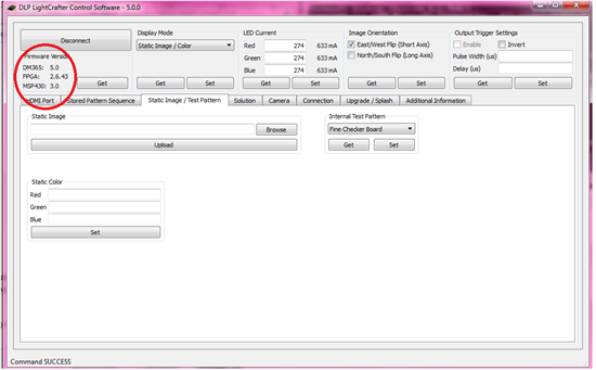
    After you succeed with upgrading the DM365 firmware and you see the latest versions in the GUI : DM365 firmware 5.0, MSP430 FW v 3.0 and FPGA v2.6.43, try setting up the pattern sequence mode and uploading the patterns. That should work.

    If it still doesn't work, send me some snapshots of your pattern sequence mode settings.

    Hope this helps.

    Regards

    Manasi

  • Thank you so much for getting back to me, Manasi.

    I have a few more questions.

    I did that and now the DLP LightCrafter is not projecting anything. It also hs removed the MSP430 and FPGA firmware software and I can't seem to re-update it. Is there any way to reset it to factory conditions?

    Also, what are the differences between NAND and booting the SD card? Does it matter which one I choose?

    Thank you so much,

    Heather

  • Just a follow-up:

    This morning when I connected the LightCrafter to the GUI, the firmware versions in the top left corner read:

    DM365: 3.31

    FPGA: XXX.XXX

    MPS430: XXX.XXX

    I have been trying to update the DM365 by using an SD card and the NAND option. I put the card in yesterday and it wasn't displaying any images. This morning, I re-uploaded the information from the _nand.dat file and put the SD card into the LightCrafter. The red light by the DM365 has been on for about an hour and no images are being projected. The DIP switch is switched towards the SD card.

    I was wondering if there is a way to just restore the inital settings and to start over with the uploads.

    Thank you,

    Heather

  • Hello Heather,

    When you boot the LightCrafter from SD Card, then DM365 is executing the U-boot and kernel from SD card and so the SD card always needs to be inserted and switch S2 needs to be in the position towards SD card.

    However when you boot LightCrafter from NAND, it copies the u-boot and kernel to the NAND and then SD card is no longer needed to be inserted and the switch S2 nows needs to be away from SD card.

    Both these methods should upgrade the DM365 firmware to the latest one 5.0 and let you connect to and start LightCrafter.

    Which of the methods did you follow? Make sure you paid attention to switch positions as per my instructions in the previous post.

    If its still not booting up, could you send me the debug/error log by connect UART cable to the PC and collecting debug log using TeraTerm?

    Regards

    Manasi

  • Hi Manasi,

    Okay, a few more questions, sorry.

    How do I connect the UART to my computer?

    Also, could you send me a sample of the image that I am suppose to be loading into the device?

    Thank you.

    Heather

  • Hi Manasi,

    I ran the debugger twice and got the following two messages. Is it possible that the debgger is picking up the information in hex which is why the output doesnt make sense?

    Any help is appreciated,

    Heather

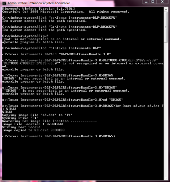
  • Also, I was using the NAND SD earlier and I just re-did the SD card with the boot. This time the LED light is blinking between red and green, but there is no image. Attached is the log of the upload to SD boot.

  • Hello again,

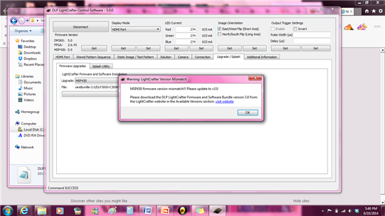
    So, since I was getting the green and red light blinking, I connected to the GUI and found the DM365 to be updated to v5.0. However, I no longer have the FPGA or MSP430 firmware installed. How can I go about fixing this issue?

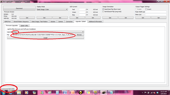
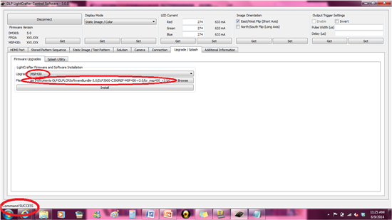
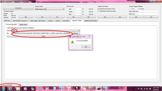
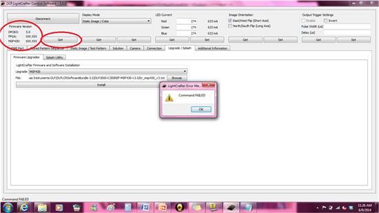
    I tried the Ugrade/Splash tabs and the commands say that they are successful for the FPGA and MSP430, but not for the EDID. And when I hit the "Get" button for the firmware, it says "Comman Failed". Attached are photos.

    Thank you,

    Heather

  • I have successfully update the firmware! but there is still no light being displayed.

    Can you tell me why there is no light being displayed and how I can fix it?

    I have tried uploading the images and they successfully upload but then they don't display (Command FAILED). I am assuming this is because there is no liht coming from the projector. How can I get the images to display?

    Thank you,

    Heather

  • Hello Heather,

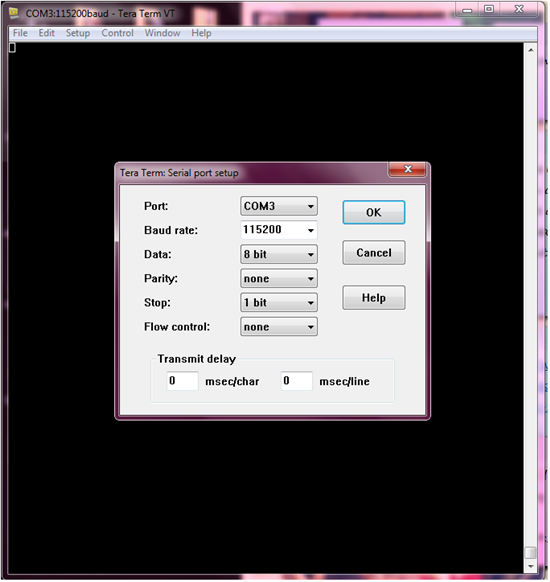
    Thanks for trying the UART debug log option. However may be the UART settings are not correct so its not generating any output.

    Could you double check the Serial port settings on Teraterm?

    It should be :

    Port : Whichever port UART to USB is connected on your PC

    Baud rate: 115200

    Data: 8 bit

    Parity: none

    Stop: 1 bit

    Flow Control: none

    You should see something like this:

    -----------------------------------------------
    LightCrafter - NAND Boot
    -----------------------------------------------
    nand_size=134217728
    u-boot src=0x00320800
    nand_read block_idx=0x00000019 page_idx=0x00000001 len=0x0002D000
    block=0000001A
    kernel src=0x00400000
    nand_read block_idx=0x00000020 page_idx=0x00000000 len=0x00300000
    block=00000038
    file-system src=0x00800000
    nand_read block_idx=0x00000040 page_idx=0x00000000 len=0x00300000
    block=00000058
    Jummping to nand bootloader


    U-Boot 2010.12-rc2 (Jan 15 2014 - 12:53:13)

    Cores: ARM 297 MHz
    DDR: 243 MHz
    I2C: ready
    DRAM: 128 MiB
    GPIO Config NAND-WP : GPIO76 as output (1)
    GPIO Config DVI-I2C-EN : GPIO73 as output (0)
    GPIO Config DVI-ENA : GPIO74 as output (0)
    GPIO Config CAM-RESETZ : GPIO102 as output (0)
    GPIO Config CAM-RESETZ : GPIO102 as output (1)
    GPIO Config CAM-DENABLE : GPIO93 as output (1)
    MMC: davinci: 0
    Using default environment

    Net: No ethernet found.
    Hit any key to stop autoboot: 0
    Card did not respond to voltage select!
    ## Booting kernel from Legacy Image at 80700000 ...
    Image Name: Linux-2.6.32.17-davinci1
    Created: 2014-01-15 19:03:17 UTC
    Image Type: ARM Linux Kernel Image (uncompressed)
    Data Size: 1619912 Bytes = 1.5 MiB
    Load Address: 80008000
    Entry Point: 80008000
    Verifying Checksum ... OK
    Loading Kernel Image ... OK
    OK

    Starting kernel ...

    Uncompressing Linux............................................................................................................ done, booting the kernel.
    Linux version 2.6.32.17-davinci1 (sanjeevmg@sanjeevmg-VirtualBox) (gcc version 4.3.3 (Sourcery G++ Lite 2009q1-203) ) #1 PREEMPT Wed Jan 15 13:03:04 CST 2014
    CPU: ARM926EJ-S [41069265] revision 5 (ARMv5TEJ), cr=00053177
    CPU: VIVT data cache, VIVT instruction cache
    Machine: DaVinci DM365 LCr
    Memory policy: ECC disabled, Data cache writeback
    DaVinci dm36x_rev1.2 variant 0x8
    Built 1 zonelists in Zone order, mobility grouping on. Total pages: 29464
    Kernel command line: mem=116M console=ttyS0,115200n8 root=/dev/ram0 rw initrd=0x82000000,5M ramdisk_size=15360 ip=off video=davincifb:vid0=1216x684x16,4050K:vid1=off:osd0=0x0x8,0K:osd1=0x0x8,0K dm365_imp.oper_mode=0 davinci_enc_mngr.ch0_output=LCD davinci_enc_mngr.ch0_mode=1216x684YUV vpfe_capture.interface=1
    PID hash table entries: 512 (order: -1, 2048 bytes)
    Dentry cache hash table entries: 16384 (order: 4, 65536 bytes)
    Inode-cache hash table entries: 8192 (order: 3, 32768 bytes)
    Memory: 116MB = 116MB total
    Memory: 108928KB available (3052K code, 244K data, 124K init, 0K highmem)
    SLUB: Genslabs=11, HWalign=32, Order=0-3, MinObjects=0, CPUs=1, Nodes=1
    Hierarchical RCU implementation.
    NR_IRQS:245
    Console: colour dummy device 80x30
    Calibrating delay loop... 147.86 BogoMIPS (lpj=739328)
    Mount-cache hash table entries: 512
    CPU: Testing write buffer coherency: ok
    DaVinci: 8 gpio irqs
    NET: Registered protocol family 16
    davinci_serial_init:97: failed to get UART2 clock
    bio: create slab <bio-0> at 0
    DM365 IPIPE initialized in Continuous mode
    vpss vpss: dm365_vpss vpss probed
    vpss vpss: dm365_vpss vpss probe success
    dm365_afew_hw_init
    ch0 default output "LCD", mode "1216x684YUV"
    VPBE Encoder Initialized
    LogicPD encoder initialized
    Switching to clocksource timer0_1
    musb_hdrc: version 6.0, cppi-dma, peripheral, debug=0
    musb_hdrc: USB Peripheral mode controller at fec64000 using DMA, IRQ 12
    NET: Registered protocol family 2
    IP route cache hash table entries: 1024 (order: 0, 4096 bytes)
    TCP established hash table entries: 4096 (order: 3, 32768 bytes)
    TCP bind hash table entries: 4096 (order: 2, 16384 bytes)
    TCP: Hash tables configured (established 4096 bind 4096)
    TCP reno registered
    NET: Registered protocol family 1
    Trying to unpack rootfs image as initramfs...
    rootfs image is not initramfs (no cpio magic); looks like an initrd
    Freeing initrd memory: 5120K
    JFFS2 version 2.2. (NAND) © 2001-2006 Red Hat, Inc.
    msgmni has been set to 223
    alg: No test for stdrng (krng)
    io scheduler noop registered
    io scheduler anticipatory registered (default)
    davincifb davincifb.0: dm_vid0_fb: 1216x684x16@0,0 with framebuffer size 4050KB
    DM365 IPIPEIF probed
    imp serializer initialized
    davinci_previewer initialized
    davinci_resizer initialized
    Serial: 8250/16550 driver, 2 ports, IRQ sharing disabled
    serial8250.0: ttyS0 at MMIO 0x1c20000 (irq = 40) is a 16550A
    console [ttyS0] enabled
    serial8250.0: ttyS1 at MMIO 0x1d06000 (irq = 41) is a 16550A
    brd: module loaded
    loop: module loaded
    NAND device: Manufacturer ID: 0xec, Chip ID: 0xf1 (Samsung NAND 128MiB 3,3V 8-bit)
    Creating 4 MTD partitions on "davinci_nand.0":
    0x000000000000-0x000000400000 : "bootloader"
    0x000000400000-0x000000800000 : "kernel"
    0x000000800000-0x000000c00000 : "rootfs"
    0x000000c00000-0x000008000000 : "data"
    davinci_nand davinci_nand.0: controller rev. 2.3
    spi_davinci spi_davinci.0: Controller at 0xfec66000
    g_ether gadget: using random self ethernet address
    g_ether gadget: using random host ethernet address
    usb0: MAC 3e:2a:2f:07:9b:94
    usb0: HOST MAC 16:c5:64:87:2e:f2
    g_ether gadget: Ethernet Gadget, version: Memorial Day 2008
    g_ether gadget: g_ether ready
    i2c /dev entries driver
    Linux video capture interface: v2.00
    vpfe_init
    vpfe-capture: vpss clock vpss_master enabled
    vpfe-capture vpfe-capture: v4l2 device registered
    vpfe-capture vpfe-capture: video device registered
    IndPico : switch to HD imager-MT9P031 video input
    vpfe-capture vpfe-capture: v4l2 sub device mt9p031 register fails
    suresh:mt9m112_probe()
    Sanjeev::MT9M112-> Probing for the camera device...
    suresh:mt9m112 : f0 <= 0
    mt9m112 : page reg write failed !!!!!!!
    mt9m112 1-0048: No MT9M11x chip detected, register read ffffff87
    Sanjeev::MT9M112-> Camera device not detected!!!
    vpfe-capture vpfe-capture: v4l2 sub device mt9m112 register fails
    mt9v113 1-003c: No MT9V113 chip detected, register read ffffff87
    vpfe-capture vpfe-capture: v4l2 sub device mt9v113 register fails
    No sub devices registered
    vpfe_register_ccdc_device: DM365 ISIF
    dm365_isif: probe of dm365_isif failed with error -22
    af major#: 252, minor# 0
    AF Driver initialized
    aew major#: 251, minor# 0
    AEW Driver initialized
    Trying to register davinci display video device.
    layer=c6678000,layer->video_dev=c6678164
    Trying to register davinci display video device.
    layer=c6678400,layer->video_dev=c6678564
    davinci_init:DaVinci V4L2 Display Driver V1.0 loaded
    watchdog watchdog: heartbeat 60 sec
    davinci_mmc davinci_mmc.0: Using DMA, 4-bit mode
    TCP cubic registered
    NET: Registered protocol family 17
    Clocks: disable unused mmcsd1
    Clocks: disable unused spi1
    Clocks: disable unused spi2
    Clocks: disable unused spi3
    Clocks: disable unused spi4
    Clocks: disable unused pwm0
    Clocks: disable unused pwm1
    Clocks: disable unused pwm2
    Clocks: disable unused pwm3
    Clocks: disable unused timer1
    Clocks: disable unused timer3
    Clocks: disable unused emac
    Clocks: disable unused voice_codec
    Clocks: disable unused asp0
    Clocks: disable unused rto
    Clocks: disable unused mjcp
    RAMDISK: gzip image found at block 0
    g_ether gadget: full speed config #2: RNDIS
    VFS: Mounted root (ext2 filesystem) on device 1:0.
    Freeing init memory: 124K
    init started: BusyBox v1.14.2 (2011-07-01 06:57:13 IST)
    starting pid 925, tty '': '/etc/rcS'
    Starting System
    done.
    Welcome to
    _ _ _ _ ____ __ _
    | | (_) __ _| |__ | |_ / ___|_ __ __ _ / _| |_ ___ _ __
    | | | |/ _` | '_ \| __| | | '__/ _` | |_| __/ _ \ '__|
    | |___| | (_| | | | | |_| |___| | | (_| | _| || __/ |
    |_____|_|\__, |_| |_|\__|\____|_| \__,_|_| \__\___|_|
    |___/

    DLP(R) Pico Development Platform
    Build host: ubuntu
    Built by: a0876512
    Build date: Fri, 24 Jun 2011 14:23:15 +0530
    Build tag: leopard
    Skipping Network Config ...
    Starting IndPico Command Handler ....
    Running LightCrafter command handler application.... build date Jan 15 2014 13:03:27

    Regards

    Manasi

  • Here are my Serial Port Settings. After hitting OK there is still no writing displayed in the TeraTerm window.

  • Hi Manasi,

    I was able to get the light to display out of the DLP LightCrafter by updating the DLPC300 firmware. However, now there is no MSP430 firmware. How can I go about getting the missing firmware?

    (I tried upgrading it from the Upgrade/Splash tab, and a message in the bottom left corner said "Command Success", but it is still giving me the error message.)

    Thank you,

    Heather

  • Nevermind. When I turned it on this morning, all of the firmware was intact and I was able to use the LightCrafter.

    As I get further along with the LightCrafter, I have a few questions about the stored patterns. How many patterns can I create and store on this device? Are the patterns then easily accessible and able to switch quickly?

    Thanks,

    Heather

  • That's a great news!

    For the stored pattern sequences, you can store upto 96 bit planes or a total of 96 1 bit depth patterns. 

    You can refer to section 2.8 of User's guide to understand how patterns can be created in the stored pattern sequence mode.

    You can refer to section 4.3 of User's guide to understand the maximum pattern rates obtained and the minimum pattern exposure times required different bit depth patterns.

    Hope this helps.

    Let me know if you have any more questions.

    Regards

    Manasi

  • I am attempting to do multiple Bit-Depth and Multiple Color Pattern Sequences and I and just using the MBMC samples from the TI website. When I get to the Image List File Browse and Import Images, a message box apears and reads "Image file coul dnot be opened or does not exsist".

    What could be the problem here?

    Thank,

    Heather

  • Is there a way that you could show me a sample image list file?

    Thanks,

    Heather

  • Hello Heather,

    I am glad you have finally got the LightCrafter up and running with all the latest software and firmware versions.

    So in order to use MBMC pattern sequences, you can submit a request for a specific pattern sequence you would like for us to create Eg: 1bppx4R_8bppx2B_2bppx6G_exposuretime_us and we will generate the required .bin file and ReadMe File for you.

    The Image list file is just a .txt file with names of .bmp files/ pattern images that you want to project. We do not supply the images, you would have to create your own composite images which would then be parsed into individual 1bpp patterns and loaded into the system.

    Refer to MBMC section 2.8.1.2 of Users guide for more details.

    Regards

    Manasi

  • HI Manasi,

    I have a few questions regarding the effiency regarding the DLP LightCrafter.

    1. When the LEDs are being used with the stored pattern sequence, do they shine at different time segments?

    2. Is there a way I can have the LightCrafter cycle through a series of stored patterns?

    3. How quickly can the image frames be changed and if the frames are chosen in an arbitray order, does this time change?

    4. Is there a way to determine the angle that the mirrors are at based on what is being displayed?

    Thank you,

    Heather