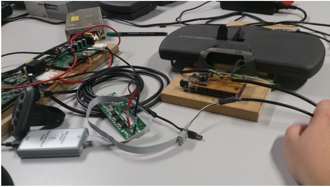
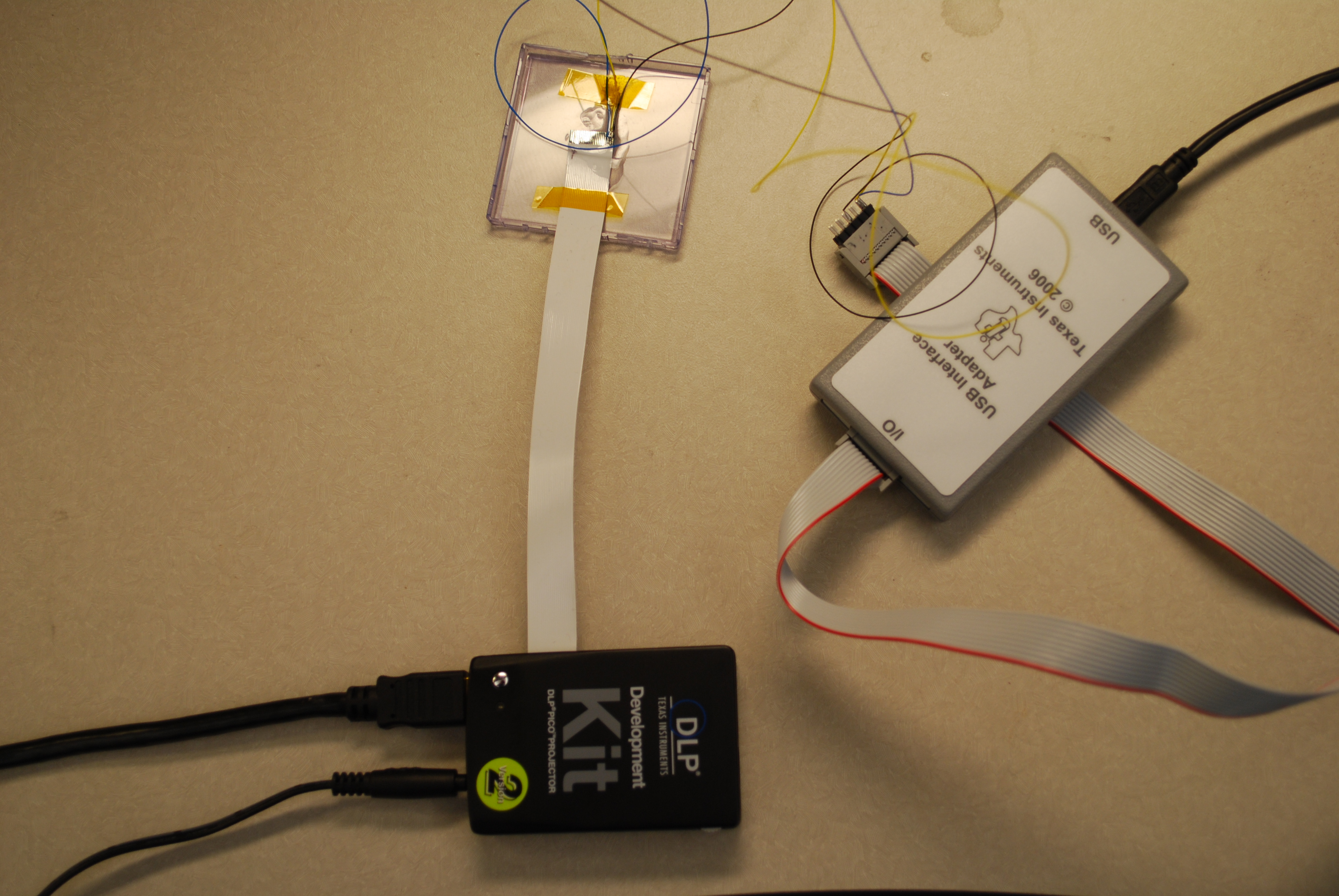
I have a Pico 2 development kit that I am experimenting with. I would like to perform some simply programming operations that configure the unit to display various internal structured light patterns. I have NOT been able to successfully execute any I2C commands. My setup is as follows: I am using a flex ribbon cable connected to the J113 Auxiliary port on the Pico 2, I have soldered fine leads to the SDA (Pin 22), SCL (Pin 23), and Ground (Pin 24), these signals are run into a TI USB I2C interface Adapter module via its ribbon cable. Interaction with the programmer/Pico is through the GUI application that came with the programmer module. The hardware arrangement is shown below -
I have a couple of active questions and a general solicitation for other possible problems.
1. The Development Kit Users Guide talks about pull-up resistors for the I2C signals. What value of resistors are required? (the programming module lists 0, 2.2K, 1.1K, and 668 ohm as options)
2. There is mention of bus speed selection. Is the Pico setup up for 100KHz or 400K Hz communication? Or does it matter?
3. The programmer's GUI application only has entries for Read vs. Write, Cmd, and Data. This does match very well with the Pico Programmers Guide descriptions about what needs to be sent out. I am assuming that the application is handling some of the details behind the scenes - or maybe this is the source of the problem. For example, if I want to designate the input source as the splash screen I need to write the value 0x0000002 to adrresss 0x04. In other words send out S 36 04 00 00 00 02 P. As you can see the GUI does not allow for entry of all of this detail. I assume that by specifying Device Address 1 and selecting the radio button I2C Write that this is where the initial 0x36 comes from.
Likewise, when reading I am assuming that selection of the I2C Read radio button causes the applicaton to follow through on the 2 step cycle for reading data. Since nothing is working - I am left with questions.
I have attached a screen shot of the programmer's GUI.

4. What address is considered the base address for I2C programming on the Pico. The programmers guide calls out 0x36 for writes and 0x37 for reads. Other documentation suggests 0x1B.
5. It appears that most developers are using the Beagle Board to manipulate the Pico. Maybe this is the path I should choose. But, I would like to get a feel for what the Pico's capabilities are before creating a real project and it seems that the approach I am trying should work.
6. I have captured the initial outbound SCL, SDA cycle to the I2C bus on an oscilloscope. It looks as expected with the exception of responding ACK.
Any other suggestions would be appreciated.
Pete