This thread has been locked.

If you have a related question, please click the "Ask a related question" button in the top right corner. The newly created question will be automatically linked to this question.

Configuring C5505 at 150 Mhz

Hi, i have my own PCB with 150 Mhz versione of C5505

I try to configure the PLL like that:

void Init_PLL_150(void)
{
//Uint16 i;
// PLL set up from RTC
// bypass PLL
CONFIG_MSW = 0x0;

// 120 Mhz
/*
PLL_CNTL2 = 0x8000;
PLL_CNTL4 = 0x0000;
PLL_CNTL3 = 0x0806;
PLL_CNTL1 = 0x8E4A;
*/
// 150 Mhz

PLL_CNTL1 = 0x03E4;
PLL_CNTL2 = 0x004C;
PLL_CNTL3 = 0x0806;
PLL_CNTL4 = 0x0000;

while ( (PLL_CNTL3 & 0x0008) == 0);
// Switch to PLL clk
CONFIG_MSW = 0x1;

// clock gating
// enable all clocks
IDLE_PCGCR = 0x0;
IDLE_PCGCR_MSW = 0xFF84;


// reset peripherals
PER_RSTCOUNT = 0x02;
PER_RESET = 0x00fb;
for (i=0; i< 0xFFF; i++);
}

but it remains in loop in the while cycle as bolded

Why?

Thanks In advance

Paolo

  • I've notified the sw team. They will post their feedback directly here.

    Best Regards,
    Yordan
  • Any Tip please, It's quite urgent....
  • Hi Paolo,

    What is your CLK_SEL value?

    And if CLK_SEL = 1, what is the CLKIN frequency?

    Else if CLK_SEL = 0, is RTC 32768Hz oscillator connected and are all RTC supplies up?

    Does the PLL work with frequencies slower than 150MHz?

    I suspect that this PLL init code is old, and should be replaced with (or at least modified to match) the latest CSL 3.08 PLL initialization. See http://www.ti.com/tool/sprc133 

    You can also see the sequence in SPRUGH5B: 1.4.3.2.6 Software Steps To Modify Multiplier and Divider Ratios

    The sequence of writing to each register is important.

    PLL_CNTL1 = 0x03E4;

    PLL_CNTL2 = 0x004C;

    PLL_CNTL3 = 0x0806;

    PLL_CNTL4 = 0x0000;

    ...should probably at a minimum be rearranged in the below order... (but see the PLL init sequence below for the best results)

    PLL_CNTL2 = 0x004C;

    PLL_CNTL4 = 0x0000;

    PLL_CNTL3 = 0x0806;

    PLL_CNTL1 = 0x03E4;


    But most importantly, this method of waiting for the PLL lock status bit to indicate "locked" must not be used: while ( (PLL_CNTL3 & 0x0008) == 0);

    Instead, you must always wait for the maximum PLL lock time of 4ms with a software loop.

    This bit is been marked as reserved in the System User's Guide for several years.

    I have pared down the CSL v3.08 PLL initialization code below for you to study below:

    =-=-=-=-

    #define TIMEOUT0                             (0x0004) //32KHz 
    #define TIMEOUT1                             (0x12c0) //12MHz 
    
    CSL_Status PLL_config(PLL_Handle hPll, PLL_Config *pconfigInfo) //modified to remove C5517 code and the handle 
    {
        volatile Uint16 timeout = TIMEOUT1;
    
        /* Force to BYPASS mode */
        CSL_FINST(hPll->sysAddr->CCR2, SYS_CCR2_SYSCLKSEL, BYPASS);
    
    	/* Set RSVD = 0 in CGCR1 */
        CSL_FINST(hPll->sysAddr->CGCR1, SYS_CGCR1_RSVD, CLEAR);
    	/*Program RDRATIO, M, and RDBYPASS in CGCR1 and CGCR2*/
    	hPll->sysAddr->CGCR2 = pconfigInfo->PLLINCNTL;
    	CSL_FINS(hPll->sysAddr->CGCR1, SYS_CGCR1_M,(pconfigInfo->PLLCNTL1 & CSL_SYS_CGCR1_M_MASK));
    	/*Program ODRATIO and OUTDIVEN in CGCR4*/
    	hPll->sysAddr->CGCR4 = pconfigInfo->PLLOUTCNTL;
    	/*Write 0806g to CGCR3*/
    	hPll->sysAddr->CGCR3 = pconfigInfo->PLLCNTL2;
        /*Set PLL_PWRDN = 0*/
        CSL_FINS(hPll->sysAddr->CGCR1, SYS_CGCR1_PLL_PWRDN, CSL_FEXT(pconfigInfo->PLLCNTL1, SYS_CGCR1_PLL_PWRDN));
    	//CSL_FINST(hPll->sysAddr->CGCR1, SYS_CGCR1_PLL_PWRDN, POWERED);
    	/* Set RSVD = 1 in CGCR1 */
        CSL_FINST(hPll->sysAddr->CGCR1, SYS_CGCR1_RSVD, SET);
    
    	if (CSL_FEXT(hPll->sysAddr->CCR2, SYS_CCR2_CLKSELSTAT))
    		timeout = TIMEOUT1; //12MHz
    	else
    		timeout = TIMEOUT0; //32KHz 
    	
    	/*Wait 4ms for the PLL to complete its phase-locking sequence*/
    	while (timeout--) ; // make sure to use "volatile" when building for relese mode
    	/* Select pll */
        CSL_FINST(hPll->sysAddr->CCR2, SYS_CCR2_SYSCLKSEL, LOCK);
    
    	return (status);
    }
    

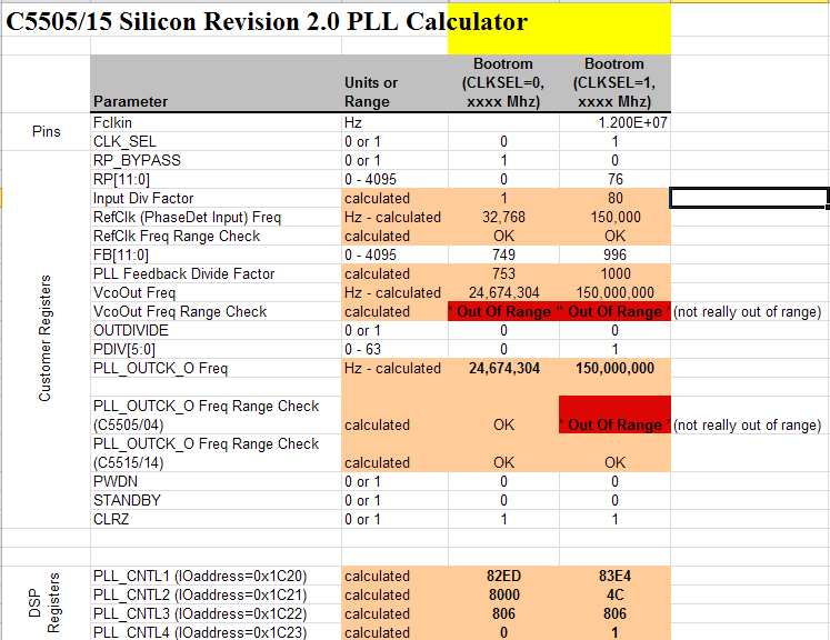
    You may also find the C5505 PLL calculator useful, but note that it is limited to 120MHz. You can still use it to program the PLL to 150MHz, but it will throw an Out of Range error.

    The out of range error when PLL_CNTL1 = 0x82ED below does appear to be a true out of range error - 24.674MHz is below the 60MHz minimum for VcoOUT/ PLLOUT (as shown in Table 1-10. PLL Clock Frequency Ranges in SPRUGH5B.

    http://processors.wiki.ti.com/images/f/f0/C5505_PLL_Calculator_060210.zip

    Hope this helps,
    Mark