This thread has been locked.

If you have a related question, please click the "Ask a related question" button in the top right corner. The newly created question will be automatically linked to this question.

Power dissipation of Filter TPS54627

Other Parts Discussed in Thread: TPS54627, TPS54327

Hi, Using Webench tool i have simulated a DC-DC Converter design with the following Requirements.

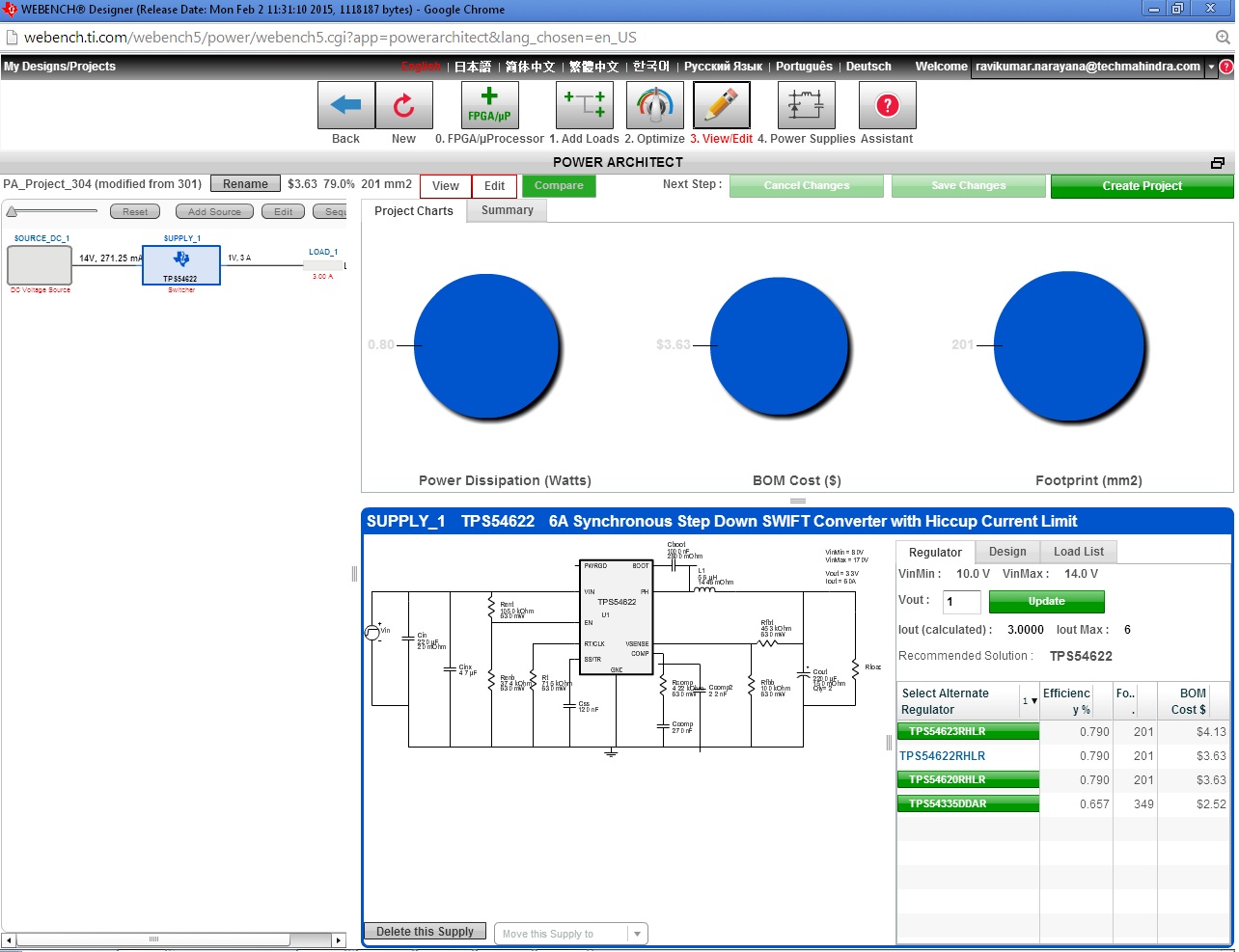
Input Voltage: 10V to 14V

Output Voltage: 1.0V @4.6A

Output Ripple: +/- 20mV.

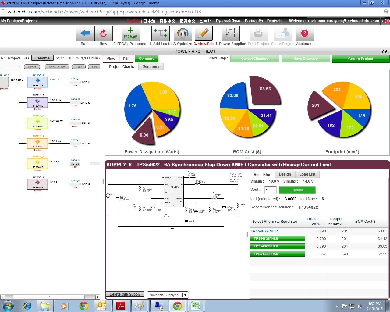
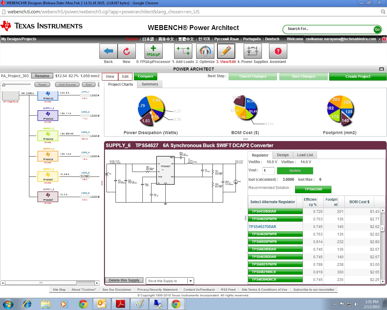
To achieve the output ripple, Webench tool has suggested to use secondary LC filter. L=150nH/11mOhm, C=4.7uF/9mOhm.

The filter power Dissipation, filter_1_Pd is given by the tool as 232.762 mW. Is there a way to find the power dissipation of the L and C components?

This info is needed for thermal management

  • Hi Ravi,
    First I want to thank you for using WEBENCH® to design your power supply. First thing to note is that when you create a new design in WEBENCH you will be taken to the visualizer screen that will show you all the possible solutions that fit your initial criteria. From here you can sort by Vout peak to peak as well as many other options, you can also export this sheet to Excel to apply a more advance searches. By searching based off Vout p-p we can see that there are many default designs that meet your Vout p-p requirement.

    The default design for the TPS54627 has a Vout p-p of 6mV which meets your desired conditions. So unless you want the extra post ripple filter for improved performance it doesn’t look like you need it based on your desired inputs.

    Now to address your initial question of how to view the power dissipation of the new L and C. You can click on the Op Vals tab and this will show the different output parameters from the current design. There is an Op Val Filter_1_Pd this is the total Pd for the new L and C. We currently don’t display the independent Pd numbers or the additional filter parts.

    However you can run the simulation and view current ripple through the inductor. With this you can make a rough guess of the Pd for the inductor based on RDCR*Irms2 and then subtract that from the Op Val Filter_1_Pd.

    One last point is since you are doing Thermal simulations consider giving the WEBTHERM tool a try by clicking on the thermal tab up at the top of your design.

    Cheers!
    -Jason
  • Hi Jason,

    Thanks for your reply.

    I have a query here.

    On ti.com webpage, 2 options are available on the Webench window.

    Multiple outputs (Power Architect) and single output.

    My requirement of DC-DC Converter is Vout = 1V@3A, Output p-p Ripple = 20mV with Input Voltage Range 10V to 14V.

    I wish to use TPS54627 for this design.

    When i tried this design in power architect with Ripple filter not selected, The Device TPS54627 did not appear in the list.

    But, when i selected the Ripple filter option, then TPS54627 appeared in the list and this design consisted of Additional Inductor and Capacitor for Filtering purposes (Higher BOM Cost)

    Whereas, when i designed with Single Output option, then in the visualizer window, TPS54627 based design is available for the required design requirement without Filter Inductor and Capacitor components.

    Can you please explain the reason for these differences even though both the designs are same?

    Thanks,

    Ravikumar

  • Hi Ravi,

    What ended up happening was that when you went to the Power Architect page and created your design, the TPS54627 was just not in the top 10 solutions.

    From the recommended solutions page in Power Architect click on the View project details button in the top right. You will then see a detailed output of the current solution. You can change what switching solution is selected in the list in the bottom right. If you scroll down a bit you will find the TPS54627 as a possible solution. It is also by default generated without the ripple filter.

    The designs created via the single output method and Power Architect are identical, the only difference are the order in which they are displayed.
    Hope this clears things up for you.

    Cheers!
    -Jason
  • Ravi,

     By the way, you can specify an output ripple spec and also a ripple filter in the single supply Visualizer step by using the new Advanced Options feature.  You can access that by clicking on the link just above the recalculate button in the Change Inputs section.  There is a brief video explaining this at the following URL: http://www.ti.com/general/docs/video/watch.tsp?entryid=1_zyzgw4ny

    Regards,
    Jeff

  • Hi Jason,

    Thanks for your reply.

    I tried the steps you had suggested in your response with Power Architect.

    Surprisingly when i tried with power architect for 1V@3A with NO Ripple Filter Option( i.e. Ripple filter Check box Unchecked). TPS54627 didnt appear in the list of Regulators.

    I have attached screen shot of the tool.

    Please let me know what has gone wrong.

    Regards,

    Ravikumar

  • Hi Ravi,

    This is interesting, are the only inputs that you are applying the basic ones (vin,vout,Iout)? If you are not selecting any advance filtering options then i must be missing something.

    Where you able to create the design in the single rail Webench interface?

    Regards
    -Jason
  • Hi Jason,

    The only inputs applied by me are Vin, Vout, Iout and Vout(p-p) %.

    Yes, i was able to create the design in the single output webench interface

    Regards,

    Ravi

    1V0@3A Single Output.pdf

  • Hi Jason,

    Today i observed a strange happening with the Webench Tool.

    Using Power Architect option, i tried to design power supplies with the following requirements.

    Vin= 10V to 14V

    Output Voltages:

    1) Vout = 3.3V, Iout = 5A, Vout (p-p) ripple = 1.5%

    2) Vout = 1.5V, Iout = 1.1A, Vout (p-p) ripple = 1.5%

    3) Vout = 1.5V, Iout = 0.6A, Vout (p-p) ripple = 1.5%, Seperate supply is used

    4) Vout = 1.2V, Iout = 1.3A, Vout (p-p) ripple = 1.5%

    5) Vout = 1.0V, Iout = 4.6A, Vout (p-p) ripple = 1.5%

    6) Vout = 1.0V, Iout = 3A, Vout (p-p) ripple = 1.5% Separate supply is used

    For all the above output voltages, Ripple filter requirement was not checked  in the check box

    For the first time when i tried to design this supply, for Vout = 1V@3A, TPS54627 was listed in the Select Alternate Regulator Column. (Power Architect 1V@3A.jpg)

    When i tried repeating the same design for the second time with identical inputs, surprisingly, for Vout = 1V@3A, TPS54627 was not listed in the Select Alternate Regulator Column. (Power Architect 1V@3A _1.jpg)

    Can you please take a look at this and explain if something went wrong from side?

    Regards,

    Ravikumar

  • Hello Ravikumar,

    We have seen this issue of inputting the same inputs and getting different outputs in Power Architect. Power Architect has a complex solution selection flow. We parallel this flow to increase the speed of the system and get the results quicker. Due to the multiple threads running at the same time the flow will return results in a non-deterministic order. Since these solution threads can come back in different orders every time you generate a design there is no guarantee that the same solution will be the number one best every time.

    We are aware that this is frustrating but we can guarantee that every design that does get created is valid every time the solution set is generated.
    We apologize for the inconveniences.

    Regards
    -Jason
  • Hi Ravi,

    I was unable to recreate this issue, I am currently working to try to find the root of this problem. As for the time being if you only have one load that you are trying to design a solution for I recommend using the single load designer.

    Regards
    -Jason
  • Hi Jason,

    Thanks for your reply.

    I intend to design power supply solution with the below requirements.

    Vin= 10V to 14V

    Output Voltages:

    1) Vout = 3.3V, Iout = 5A, Vout (p-p) ripple = 1.5%

    2) Vout = 1.5V, Iout = 1.1A, Vout (p-p) ripple = 1.5%

    3) Vout = 1.5V, Iout = 0.6A, Vout (p-p) ripple = 1.5%,

    4) Vout = 1.2V, Iout = 1.3A, Vout (p-p) ripple = 1.5%

    5) Vout = 1.0V, Iout = 4.6A, Vout (p-p) ripple = 1.5%

    6) Vout = 1.0V, Iout = 3A, Vout (p-p) ripple = 1.5% 

    Also, I want to use TI Regulators TPS54327 and TPS54627 only for this design.

    I used TI’s Webench tool to generate this design.

    I used single output option to design each of these voltages.

    Webench tool generated the design with TPS54327/ TPS54627 (whichever was appropriate for the load current) for each of these rails. In the design post filter stage was not recommended.

    Now, as per my understanding, I can parallel/combine these individual circuits to design the necessary complete solution for my requirement (i.e. in Power Architect Fashion).

    Please let me know whether my understanding is right?

     Regards,

    Ravikumar

  • Hi Ravi,

    In order for me to better assist you we should take this off the forums.

    Please email me at: j-lambert@ti.com

    Regards
    -Jason