This thread has been locked.

If you have a related question, please click the "Ask a related question" button in the top right corner. The newly created question will be automatically linked to this question.

TCA9546A: Device tree structure for multi level i2c switch

Part Number: TCA9546A

Hi, 

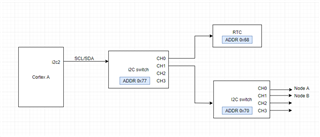
In our application we have a TCA9546A with addr 0x77 connected to the core i2c2 of Cortex A running Ubuntu. We are able to probe devices connected to Channel 0 of the switch 0x77. On Channel 1 we have another i2c switch with addr 0x70. We are having issues probing the switch with addr 0x70. I was wondering if you have any documentation or support related to device tree implementation for mult-level i2c switches as in our case. 

Thanks,

Nikhil

  • Hi Nikhil,

    Can you elaborate on what you mean by probing the switch with addr 0x70? Do you just mean that it is not recieving I2C commands?

    • Did you check the VOL/VIL of each device to make sure they are compatible with each other?
    • Do you have pull up resistors installed?
    • Did you make sure that your SDA and SCL pins are correctly placed?

    Let's start from there and we can continue to debug the issue.

    Best,

    Chris

  • On Linux boot up, the i2cmux driver gives an error: 'pca954x 6-0070: probe failed'.

    For one of our other projects, we have the same switch 0x70 connecting directly to the core i2c2 (basically without switch 0x77 in the middle) and that works fine. So all the three points you mentioned are true. Its only when we added a switch in the middle that we are facing the issue.

    I was wondering if my device tree structure is not right. For the second switch i use regular addressing as I did for the first switch.

    Do you think i would have to use two cell addressing in order to access the second switch nodes? Basically something like this:

            mux at 77 {
    
                    #address-cells = <2>;
    
                    #size-cells = <0>;
    
                    compatible = "philips,pca9547";
    
                    reg = <0x77>;


                    mux at 0,70 {
    
                            #address-cells = <2>;
    
                            #size-cells = <0>;
    
                            compatible = "philips,pca9547";
    
                            reg = <0 0x70>;
    
                    };


                    mux at 0,71 {
    
                            #address-cells = <2>;
    
                            #size-cells = <0>;
    
                            compatible = "philips,pca9547";
    
                            reg = <1 0x71>;
    
                    };
    

    The above code is not what I have but I wanted to check with you if that is the right structure? You can find this in the following link:
    https://lists.ozlabs.org/pipermail/devicetree-discuss/2011-May/005523.html

    Thanks,
    Nikhil
  • Hi Nikhil,

    I believe this question is outside the scope of this forum. I am more than happy to answer your questions about the I2C device itself but I am not familiar with getting a Linux system to interface with this device. I won't be able to advise you on what cell addressing to use. I have notified another I2C expert of this thread. If they know anything about this topic they will let me know.

    This is some documentation I was able to find on device trees and LInux: https://elixir.bootlin.com/linux/v4.9.28/source/Documentation/devicetree/bindings/gpio/gpio.txt

    Once again, I am not sure if it pertains to your issue since I am unfamiliar with Linux device trees. If you need any help in debugging the device or testing the switch to make sure it works let me know. I can definitely assist you in that.

    Best,

    Chris

  • You have not shown your device tree, so we cannot tell you what's wrong with it.

    It should probably look like this:

      i2cmux@77 {
        #address-cells = <1>;
        #size-cells = <0>;
        compatible = "nxp,pca9546";
        reg = <0x77>;
        i2c@0 {
          #address-cells = <1>;
          #size-cells = <0>;
          reg = <0>;
          rtc@68 {
            compatible = "...";
          };
          i2cmux@70 {
            #address-cells = <1>;
            #size-cells = <0>;
            compatible = "nxp,pca9546";
            reg = <0x70>;
            i2c@0 {
              #address-cells = <1>;
              #size-cells = <0>;
              reg = <0>;
              ...
            };
            i2c@1 {
              #address-cells = <1>;
              #size-cells = <0>;
              reg = <1>;
              ...
            };
          };
        };
      };

  • I apologize for not sharing my device tree earlier. I am attaching my device tree implementation for the i2c mux. The structure syntax is similar to what you have shown. I am still unable to access the second I2c switch. Please let me know if you find anything wrong with my approach. 

    &i2c2 {
    
    	
    	tca9546: i2c2mux9546@77 {
    		compatible = "nxp,pca9546";
    		pinctrl-names = "default";
    		pinctrl-0 = <&pinctrl_i2c2_SWgrp>;
    		reset-gpios = GP_I2C2_SW_RST;
    		reg = <0x77>;
    		status = "okay";
    		#address-cells = <1>;
    		#size-cells = <0>;
    
    		//on board peripherals
    		i2c@0 {
    			clock-frequency = <100000>;
    			reg = <0>;
    			#address-cells = <1>;
    			#size-cells = <0>;
    		      
    			rtc@68 {
    				compatible = "...";
    			};
    		};
    		
    	
    		//Display subsystem
    		i2c@1 {
    			clock-frequency = <100000>;
    			reg = <2>;
    			#address-cells = <1>;
    			#size-cells = <0>;
    
    			status = "okay";
    	
    			Device1@2c {
    					compatible = "..."
    					reg = <0x2c>;
    					status = "disabled";
    			};
    
    
    			Device2@38 {
    				compatible = "...";				
    				reg = <0x38>;
    			};
    
    			Device3@5d {
    				compatible = "...";				
    				pinctrl-names = "default";
    				reg = <0x5d>;				
    			};
    
    			Device4@40 {	
    				compatible = "...";			
    				pinctrl-names = "default";				
    				reg = <0x40>;				
    			};
    
    			Device5@41 {
    				compatible = "...";
    				reg = <0x41>;
    			};
    
    			Device6@55 {
    				compatible = "...";				
    				pinctrl-names = "default";
    				reg = <0x55>;
    			};
    
    			 i2cmux9546@70 {
    			 	compatible = "pca9546";
    			 	reg = <0x70>; 	
    				#address-cells = <1>;
    			 	#size-cells = <0>;
    
    			 	i2c@0 {
    			 		clock-frequency = <100000>;
    			 		reg = <0>;
    			 		#address-cells = <1>;
    			 		#size-cells = <0>;
    
    			 		Device7@48 {
    			 			compatible = "..." ;			 			
    			 			reg = <0x48> ;						
    			 		};
    			 	};
    
    			 	i2c@1 {
    			 		clock-frequency = <100000>;
    			 		reg = <1>;
    			 		#address-cells = <1>;
    			 		#size-cells = <0>;
    					
    			 	};
    
    			 	i2c@2 {
    			 		clock-frequency = <100000>;
    			 		reg = <2>;
    			 		#address-cells = <1>;
    			 		#size-cells = <0>;
    
    					
    			 	};
    
    			 	i2c@3 {
    			 		clock-frequency = <100000>;
    			 		reg = <3>;
    			 		#address-cells = <1>;
    			 		#size-cells = <0>;


    			 		Device8@6c {
    			 			compatible = "...";
    			 			gpio-controller;
    			 			reg = <0x6c>;
    						#gpio-cells = <2>;
    					
    			 		};
    			 	};
    
    
    			};
    
    
    		};
    
    	
    		i2c@3 {
    			clock-frequency = <100000>;
    			reg = <3>;
    			#address-cells = <1>;
    			#size-cells = <0>;
    
    		};


         };
                  
    };


    Thanks

  • Shouldn't the reg value be 1?

    		//Display subsystem
    		i2c@1 {
    			...
    			reg = <2>;