This thread has been locked.

If you have a related question, please click the "Ask a related question" button in the top right corner. The newly created question will be automatically linked to this question.

SN65DSI86: Check eDP impedance for SN65DSI86

Part Number: SN65DSI86
Other Parts Discussed in Thread: HD3SS214

Hi TI support team

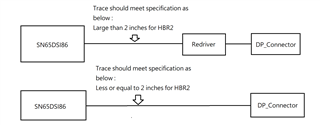
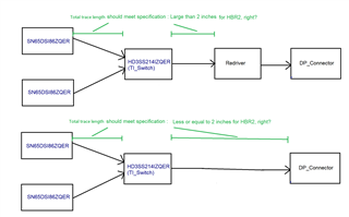
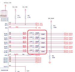
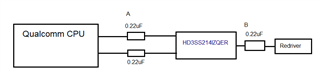
1. We know eDP impleance is 100 ohm (+-20%) from datasheet guideline.

    Could we design 90 ohm (+-10%) for eDP impedance?

2. Just double checked, for eDP signal

     A. eDP intra-lane match (P&N) < 5 mil

     B. eDP inter-lane match < 50 mil

     C. eDP_AUX intra-lane match (P&N) < 70 mil

     am I right?

Thanks

  • Hi,

    1. 90ohm +/- 10% differential impedance is ok.

    2. eDP intra-pair skew < 5mil 

    Where did you get the inter-pair skew for the eDP and intra-pair skew for AUX requirement? I would keep the skew as low as possible.

    Thanks

    David  

  • Hi David

    Thanks for your response. I will check where get the spec.

    Could you provide spec as below :

    A. eDP inter-lane match

    B. eDP_AUX intra-lane match (P&N)

    Thanks

  • Hi,

    A. eDP inter-lane match -> DisplayPort spec allows max of 2UI, but I will keep the inter-pair skew as low as possible.

    B. eDP_AUX intra-lane match (P&N) -> I will recommend 5mil

    Thanks

    David

  • Hi David

    1. Do you mean UI : Unit Interval?

    2. Could you help to provide specification directly for eDP inter-lane match ?

    Thanks

  • Hi,

    Correct, UI is unit interval. 

    For example, The UI for high bit rate (2.7Gbps/lane) is 370 ps (nominal), so 2UI = 740ps.

    Assuming 180ps/in propagation delay, the distance is 740/180 = 4in. But the propagation delay depends on the PCB material, the trace routing (stripline or microstrip), etc. This is why the spec defines the skew in terms of UI, not the actual trace length.

    Thanks

    David

  • Hi David

    Thanks for your explanation.

    I understand the inter-pair skew as low as possible.

    But we still need reference value for inter-pair of layout guide, could you sugest the value?

    I set eDP inter-lane match < 20mil, is it OK?

    Thanks

  • Hi,

    As long as the eDP panel is DP spec compliant, then I don't see this as an issue.

    Thanks

    David

  • Hi David

    I have another question.

    I see description in datasheet : 

    Maximum trace length over FR4 between SN65DSI86 and the eDP receptacle is 4 inches for data
    rates less than or equal to HBR (2.7 Gbps) and 2 inches for HBR2 (5.4 Gbps).

    Our design have redriver on eDP, do it mean trace length is less than 2 inches for HBR2 from SN65DSI86 to redriver?

    Thanks

  • Hi,

    It depends on the redriver RX equalizer capability and the placement of the redriver. But the trace is not less than 2in because you are using a redriver.

    Thanks

    David

  • Hi David

    1. If we don't use redriver

        The eDP trace length is "less or equal" to 2 inches for HBR2 between SN65DSI86 and DP connector. Am I right?

    2. If we use redriver

        The eDP trace length is "large" than 2 inches for HBR2 between SN65DSI86 and redriver. Am I right?

    Thanks

  • Hi David

    To avoid misunderstanding, I upload the picture. Please help to check it.

    Thanks

  • Hi David

    Please use the block diagram. Please help to check it.

    Thanks a lot

  • Hi,

    1. If we don't use redriver

        The eDP trace length is "less or equal" to 2 inches for HBR2 between SN65DSI86 and DP connector. Am I right? -> Correct

    2. If we use redriver

        The eDP trace length is "large" than 2 inches for HBR2 between SN65DSI86 and redriver. Am I right? -> Correct, and the eDP trace length is dependent on the redriver RX equalizer capability 

    3. If you are using HD3SS214 and the redriver, the total trace length can be more than 2in. But HD3SS214 introduces certain amount of insertion loss, so the redriver RX equalizer needs to compensate both the loss of the trace length and the loss of HD3SS214.

    4. If you are using HD3SS214 without redriver, the trace length needs to be less than 2in because HD3SS214 has certain amount of loss.

    Thanks

    David 

  • Hi David

    Thanks for your great support.

    Could you provide specification for Cap?

    Could we follow Industry spec 75nF~265nF?

    Thanks

  • Hi David

    Do you have any experimence on this?

    Do we set A=0.22uF, B=0.22uF, let DP signal AC coupling about 0.1uF to meet industry spec(75nF~265nF)?

    Trace length is 6300mil between CPU and HD3SS214IZQER

    Trace length is 400mil between HD3SS214IZQER and redriver.

    Thanks again for your checking.

  • Hi,

    If Qualcomm CPU common mode voltage is between 0 to 2V and redriver common voltage is outside the 0-2V range. In this case, connection between the CPU and the HD3SS214 is DC coupled, and HD3SS214 to redriver is AC coupled.

    If redriver common mode voltage is between 0 to 2V and CPU common mode voltage is outside the 0-2V range, then you can AC coupling the interface between the CPU and the HD3SS214, and leave the interface between the HD3SS214 and the rerdriver DC coupled.

    If the CPU and redriver common mode voltage is between 0-2V, then you can AC coupling either side of the HD3SS214, and leave other side DC coupled. 

    The AC coupling cap value follow the DP spec of 75-265nF and typical value can be 100nF or 220nF.

    Thanks

    David