Because of the Thanksgiving holiday in the U.S., TI E2E™ design support forum responses may be delayed from November 25 through December 2. Thank you for your patience.

This thread has been locked.

If you have a related question, please click the "Ask a related question" button in the top right corner. The newly created question will be automatically linked to this question.

THVD1450: A and B signals are not inverted, they are identical.

Part Number: THVD1450

Hi Team,

May I ask for your help? Please see below for customer's full transcript of inquiry:
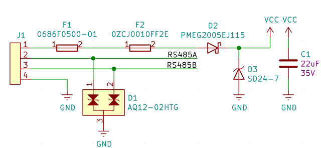
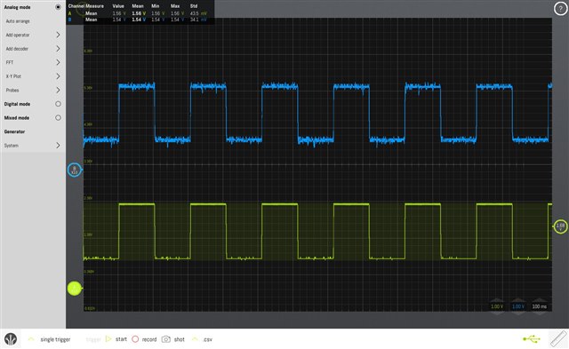
"I am developing with THVD1450 and the A and B signals are not inverted when transmitting (I did not even try receiving yet). This does not work with either UART communication (MCU TX connected to D and MCU RX connected to R) or with simple GPIO manipulation (the MCU holds the DE pin HIGH while toggling the D pin).
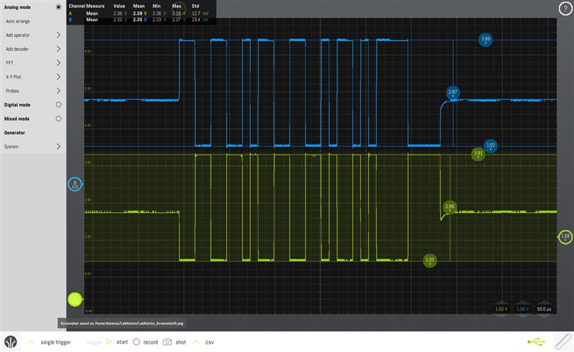
The screenshot of the scope and the schematic are in the attachments.
The A and B signals are identical no matter what I do.
 "

I hope you can help us. Thank you so much in advance.

Kind regards,

Gerald

  • Hi Gerald,

    It's possible that one of these outputs is not properly connected to the board. The floating net would then follow the driven signal via the termination resistor. Could you verify that both A and B pins are solidly connected to the board and scope? Depending on the polarity of the resulting signal, you can determine which pin is not driving correctly. Also, you may be able to zoom in on the signal transition to see if one signal lags behind the other. 

    Let me know if you have any more questions in the meantime.

    Regards,
    Eric Schott

  • Hello,
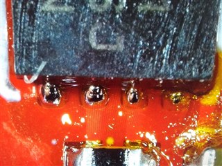
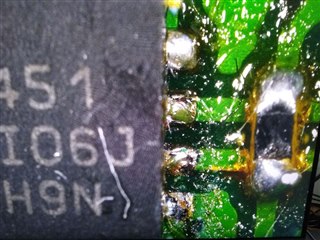
    I had a look at the solder joint under a microscope, and I think the joints are good. I have this issue with two prototype devices (same schematic, very similar PCB layout), and they were both assembled using a cheap reflow oven. Unfortunately, I don't have any other means of verifying the quality of the solder joint, but I think they look OK.
    The ICs are from the same reel. Unfortunately, with the IC shortage, I was unable to order any more to try to just replace them.


    The pictures in the last post were taken from probing the green device when I just tried toggling the GPIO after I discovered the problem on the red device where I was sending a byte.


    I tried to have a look at the transient, but the best I could do was 50us/div, and no lag was noticeable, but I suppose the lag would be faster than that. I can get my hands on a better scope maybe in a week or so and investigate this further if needed.

    Finally, I tried removing the termination resistor, and nothing much changed. The B signal just got "uglier" and the LOW dropped to 0V, while the A signal remained unchanged.

    The pictures are stored here if you needed better detail (https://imgur.com/a/CmDmYPc).

    Thank you very much for your help.

    Regards
    David Zaitlik

  • David,

    Could you do a couple of more experiments for debugging purpose? 1) do you see any difference on Icc between green and red units? 2) can do put some signal at A/B pins (for example Figure 25 in the datasheet) to see if the receiver works normally? 3) can you check the short current (Ios) for A/B pins? Or if you have the equipment, can you check the I/V curves of A/B pins? 

    Semiconductor curve tracer - Wikipedia 

  • Hi.
    1) The red and green units have different MCUs as well as everything other but the transceiver. The difference would be hard to compare, so it won't help us much.

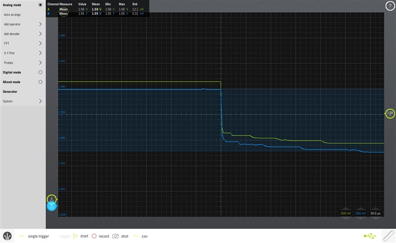
    2) The results of this can be seen in the following pictures.
    I tried with pins initialized as UART with internal pullups and DE pulled LOW and the signal is held at around 1.5V (The MCU operates at 3V3). MCU UART communication works OK when I solder some wires on the signals and connect them to an FTDI USB-UART converter.

    I tried the same but with MCU pins left floating (not initialized). Some signal is visible:


    Maybe it is the MCU making the problems? I will try as soon as I get to my hot air station. I will desolder the MCU and try again. I also ordered some SN65HVD72DRBR transceivers.

    3) I tried to measure the short current Ios both with DE LOW; and DE and D HIGH.

    I didn't really understand which short current  to measure, so I measured more combinations:

    3a) Short-current of A and B shorted:
    I didn't manage to measure anything (it was 0 in both). But I scoped it when the DE and D were held HIGH and the difference between those two signals (yellow signal) is around 50mV:

    3b) Short-Current of A/B shorted to GND
    Then I measured the short current A-GND and B-GND which were both 23uA.

  • David,

    Thanks for your information. Let's focus on the difference between A and B of problematic device while referring a normal device. 

    Can you power on the device with D=H, DE=H, REB=L, then measure A pin current while forcing the pin voltage from 0V to Vcc? If it's hard to measure the current, you can add a small series resistor (10Ohm or 1Ohm) then measure the voltage drop of the resistor. The setup looks like

    pin A ----- 10Ohm resistor ----- voltage source (0V to Vcc)

    You can repeat the measurement on pin B. 

    Similarly set D=L, DE=H, REB=L, do do measurement on A and B. 

    The intention is to see if the pin shows any abnormal (open/short) characteristics.  

  • Hello,
    sorry for the late reply, I was on vacation.

    I verified the problem is not on the PCB, since I replaced the transceiver with SN65HVD72DRBR and now it works normally and I am able to communicate with a computer.

    I can do the test on another assembly of one of the devices.