This thread has been locked.

If you have a related question, please click the "Ask a related question" button in the top right corner. The newly created question will be automatically linked to this question.

DS250DF230: Maximum achievable copper trace length with Re-timer for 25G applications

Part Number: DS250DF230

I am planning to use a DS250DF230 re-timer as mentioned in the image below for the SFP connector reach extension.

Design Specifications :

     PCB material FR4 - (FPGA, SFP connector).

     Interface speed - 25Gbps

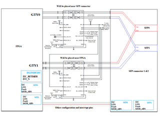
Connection : FPGA <-> Mid Plane connection <-> SFP connector (front port) . RX path re-timer will be placed near the FPGA and TX path Re-timer will be near the SFP connector. 

My design constraint is that the SFP connector needs to be placed 400mm apart from the FPGA. Is it possible to achieve this trace length with the above-mentioned combination?

What is the maximum trace length we can achieve in this method?

  • Hi Nhandakumar, let's break it down into the two cases, SFP28 egress and SFP28 ingress.

    • You have the 400mm routing constraint. This translates to 40cm or 15.75 inches. The approximate total insertion loss for FR4 trace of this length is -27.8dB (around ~1.77dB/inch)
    • For SFP+ egress
      • In this case the host retimer Tx output measured after the SFP28 connector must comply with standard. 
      • IEEE CAUI-4 "chip to module" defines a worst case host channel loss of 10dB. The retimer tx FIR post-cursor tap is able to compensate for that worse case loss (TI data shows the retimer Tx FIR can compensate up to 12dB of insertion loss at 25Gbps). But i'd suggest if feasible to air on conservative side if feasible for your board routing and allocate 8dB max to allow yourself some margin
    •   
    • For SFP+ ingress
      • The TI retimer Rx EQ (CTLE + DFE) can typically compensate for up to 35dB insertion loss at 25Gbps. So, 27.8dB input channel insertion loss or less should not be an issue for the TI retimer

    Regards,

    Rodrigo Natal

    HSSC Applications Engineer

  • Hi Rodrigo Natal,

    Thanks for the information.

    1. Is there any SI analysis done to verify the distance change with this re-timer.

        If yes please share the details of them.

    2. In SMBus Slave Mode (Without EEPROM method) what are the default initialization values we need to have of quick start functionalities.

    3. Can we connect this retimer to the I2c bus and can that i2c bus be shared with other peripherals.

  • Hi Nandha,

    1. TI performed test validation with lossy input channels to confirm the retimer RQ compensation.For your own analysis you may request retimer IBIS-AMI models via the TI.com product page and perform simulations with the channel models for your system
    2. I would suggest to download the retimer programmer's guide. You may request access for it via the TI.com product page (see link below. By default the retimer CDR is set to lock to 25.78125Gbps and Rx EQ adapt mode 1 (CTLE only.) For your case I would recommend to use adapt mode 2 (CTLE + DFE enabled)
    3. Yes. The retimer slave address is set via its ADDR pins strap option. If the I2C bus is shared with other devices you simply need to make sure all slaves have distinct addresses

    Thanks,

    Rodrigo Natal