This thread has been locked.

If you have a related question, please click the "Ask a related question" button in the top right corner. The newly created question will be automatically linked to this question.

TPS65987DDK: Setting up the schematic and configuration tool for Source 100W

Part Number: TPS65987DDK
Other Parts Discussed in Thread: TIDA-050012, TPS65987, , TPS65987D, LM3489

Hi,

I am designing a USB3.2 Gen 2 Hub with PD capabilities to 100W. One of the DFPs with be the source PD port with data. 

I've been following the Hardware design guidelines and the schematic for the EVM Power Duo (TIDA-050012) pretty closely. 

I have several question about how to set the schematic up along with the configuration tool to accomplish our goals.

1) We are good with the default 4 PDOs. But I don't see a PDO for 20V 5A, how does that work? Does this only happen with E-Marked cable? Is there any settings necessary to make this PDO available?

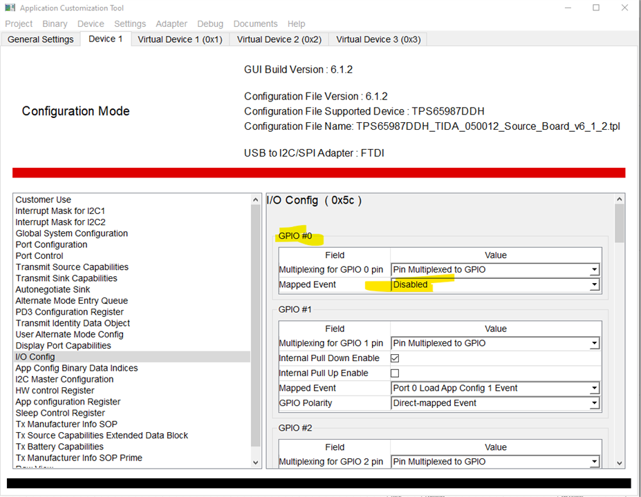
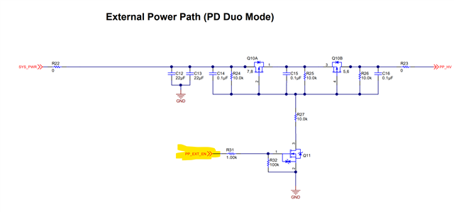
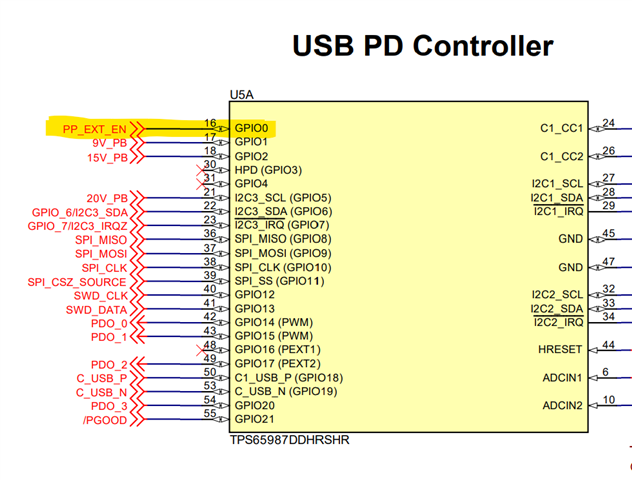
2) What GPIO should I use to turn on the external power path required for 20V 5A? From what I can tell there is many options.

3) What pins are required for programming the TPS65987? I see on the TIDA-050012 schematic both I2C 1 and 2 channels are present along with SPI to a header. Are all these pins required to program this IC?

4) Is the SPI Flash IC required for this PD controller?

Thanks any help will be much appreciated.

Mark

  • Hi Mark,

    1. You will need to either add a new PDO for 20V 5A or update the existing one to 5A

    2. Please refer to the Power DUO board on how to control the power path. You can load the project file used on the Power DUO board using the TPS6598x configuration tool https://www.ti.com/tool/TPS6598X-CONFIG 

    3 & 4. The external SPI flash is required for each TPS65987DDK device. You would program this external EEPROM using a series of header pins

  • 1.) Ok so a PDO needs to be added to support the 5A function

    2.) I looked into this and I notice in the configuration file for the Source Power DUO GPIO O is disabled, but this is the same GPIO in the schematic that is used to turn on the external power path for 5A.

    3.) Do I need just the I2C channel 1 pins to programmed this IC with the configuration tool? Or the I2C channel 2 pins and SPI pins are also required?

    4) Ok 

  • sorry forgot to include the image about the configuration tool:

  • Hi Mark,

    2. The internal power paths are used on the source and sink power duo boards. So there is no need for GPIO control. 

    3. You need to connect the SPI pins of the TPS65987D to an external SPI EEPROM. You will flash a binary image onto the EEPROM, and the PD controller will pull this image from the EEPROM during each power up

  • if those boards use the internal power path how are they capable of 5A. The datasheet clearly states the external power path is required for 5A. 

    Some information seems to be missing here.

    Also, we program the EEPROM throught the automatic configuration tool or through something else. Why are we connecting the PD controller to the automatic configuration tool if the EEPROM isn't program through the PD controller.

    A detail answer would be much appreciated. 

    Mark

  • External power path Point up

  • Follow the PP_HV power path. This is the output of the LM3489 which is the DCDC controller of the EVM (U2). You can see that this PP_HV signal goes to PPHV1 and PPHV2 of the TPS65987D. And then both of the VBUS pins are shorted together. This is because both of the internal power paths (PPHV1 and PPHV2) are put in parallel mode together for the Power DUO mode to help reduce the RDSon of the power path. 

    So there is no need for the external power path control, which is why this GPIO is disabled in the configuration