This thread has been locked.

If you have a related question, please click the "Ask a related question" button in the top right corner. The newly created question will be automatically linked to this question.

DP83825I: Register Values after Reset wrong

Part Number: DP83825I
Other Parts Discussed in Thread: USB-2-MDIO, DP83825EVM

Hello everyone,

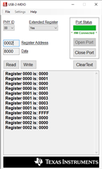
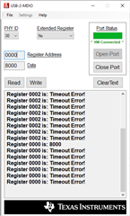
I am using the DP83825EVM as a Phy Layer for my solution. I had some problems recently with accessing the registers and it was working before without any problems. The Register Values after Reset were according to the Datasheet. I then switched to the USB-2-MDIO software to read the same registers and they still give the wrong values.

I have tried all the possible Phy Address but not change. I was wondering if someone has experienced that before and if they found the source of the problem?

Thank you

Regards

Anns

  • Hello Anns,

    Thank you for the query.

    Is there a schematics that we could quickly review. Can you make sure the clock and the supply is stable before releasing the device from reset.

    Cal you please list some of the registers you are trying to read .

    Do you have the required terminations for the MDIO interface.

    Regards,

    Sreenivasa

  • You can find the schematics here.

    https://www.ti.com/lit/df/snlr041a/snlr041a.pdf?ts=1629957510190

    The registers I am trying to read are from 0x0 to 0x3.

    The MDIO Interace is terminated correctly.

    Thank you

  • Hello Anns,

    Thank you for the inputs.

    Are you using the EVM? If yes can you please check if all the jumpers are placed as per the EVM user guide and the power supply indications are shown

    Regards,

    Sreenivasa

  • Yes I am using the EVM and the Jumpers are in there correct positions.

    When the board is powered by USB the VDDIO is supplied through where? Because I am getting timeout error with this setting.

    With VDDIO set external I can read values but they are still incorrect. Does that make sense?

  • Hello Anns,

    Thank you for the inputs.

    J2,J3, J4, J5 should have the jumpers mounted at 1..2

    Could you please elaborate what do you mean by VDDIO set external ?

    Also in the USB2MDIO can you please select extended register as no and check.

    Regards,

    Sreenivasa

  • Yes the jumper settings are correct. But one thing that I have observed is that when the VDDIO is coming from VDDIO_EXT then I get the wrong value of the register. If VDDIO_EXT is 3V3 of course.

    But if it is set to 3V3_IO_LDO then the read comes back with TimeOut Error

    Also the test was done with Extended Register set to No

    Thank you

    Anns

  • Hello Anns,

    Thank you for the inputs.

    Can you please change R7 to 0R and test.

    Alternatively can you please connect external supply between pin 2 and pin 3 of J2 and have all the jumpers set to internal supply - J3, J4, J5 should have the jumpers mounted at 1..2

    Regards,

    Sreenivasa

  • I understand that, that would be only way to test the board. An external supply. I will get one hopefully tomorrow.

    Please can you answer the following:

    1. With the USB as source why is it that the VDDIO doesn't get enough power? It should work fine shouldn't it?

    2. What are the electrical characteristics for the power supply? How much current should it be able to provide?

    This board used to work totally fine but stopped to work suddenly. But honestly we didn't try the USB 2 MDIO Software before. So I don't if that setup work ever at all, but we did access the registers over the MDIO Interface through our FPGA. So it work at one point. Should I disconnect all the cables before using the USB 2 MDIO software.

    Its really hard to make some sense of it. It is more of guessing game at this stage now. Please help me understand what is going on.

  • Hello Anns,

    Thank you for the message.

    If you change R7 to 0R, USB source would work. There is not issue with current sourcing.

    A 5V, 300mA source should be fine. The voltage can be a bit higher since we have a regulator.

    Did you connect external supplies  when you connected to the FPGA board?

    I would suggest that you disconnect all the cables to the FPGA, make the 0R changes and do a quick test,

    Regards,

    Sreenivasa

  • Hello Kallikuppa,

    thank your for help, disconnecting all the cables did work. Which is actually very surprising because removing the data cables didn't change anything. But I think the key was to remove the VDDIO External suppy on J8 Pin3. So in conclusion on the EVM VDDIO_EXT doesn't work.

    I didn't remove R7 it still worked.

    So thank you once again for your full support.

    Regards

    Anns

  • Hello Anns,

    Thank you for the inputs and happy to support you. Let me summarize the settings.

    You have all the jumpers configured for internal supply and using the USB interface to communicate as well as supply the power.

    Thanks,

    Sreenivasa

  • Yes, but not with supply power I didn't need that anymore. It works fine with the USB supply.

    Thank you.

  • Hello Anns,

    Thank you for the inputs.

    Regards,

    Sreenivasa