A related question is a question created from another question. When the related question is created, it will be automatically linked to the original question.
If you have a related question, please click the "Ask a related question" button in the top right corner. The newly created question will be automatically linked to this question.
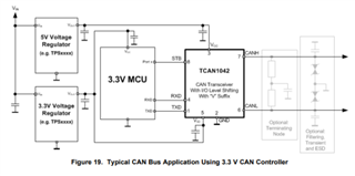
It looks like the supply to Vcc in this schematic is to a 3.3V source. TCAN1042 is a 5V transceiver and requires at least 4.5V on the Vcc supply to be functional. Was this meant to be connected to a different supply rail in the schematic? Or would you prefer to use a 3.3V CAN transceiver?
Apart from the supply voltage and TVS placement (see below), this schematic looks good.
Decoupling capacitors included and valued appropriately.
Split capacitor included and valued appropriately.
Bus capacitors included and valued appropriately - ensure placement close to connector and along signal path.
TVS diode included - ensure placement close to connector and along signal path.
Recommend placement on connector-side of CMC. This facilitates proximity to board connectors.
Termination resistors included correctly and valued appropriately.
All pull-up / series resistances are acceptable.
Let me know if you have any questions or concerns.
Rx and Tx (UART port )which are coming from the MCU to CAN, do we need to swap it (Rx to Tx ,Tx to Rx)or need to connect one to one (Rx to Rx ,Tx to Tx)
The TXD pin is a digital input and expects to be driven between 0V and Vio. The RXD pin is a push-pull output that will drive between 0V and Vio. Typically this will match the naming convention of the MCU (one to one as you described second).
For use with non-CAN protocols, keep in mind that the transceiver has a dominant timeout feature. This will prevent the transceiver from driving a dominant signal (logic 0) for longer than ~1ms. Make sure the UART data and idle state accommodates for this restriction.
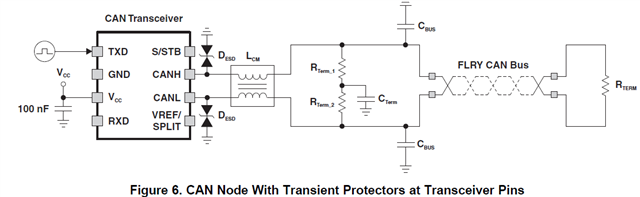
During short circuit to dc voltage conditions on the CAN bus, the high transients are seen in the system between the common-mode choke and the transceiver. The first application workaround is to move the transient protectors from the connector side to the transceiver side of the choke, as shown in Figure 6. This circuit effectively clamps all transients before the transceiver, allowing for the best system-level protection.
please lets us know you view on the TVS diode location
There is a trade-off in whichever method is used here. Placing the ESD protection next to the device pins ensures that any conditions created by the CMC can be addressed by the diodes. However, the energy introduced by the ESD or surge event will still propagate through the board, potentially impacting other components or parts of the system. With TVS diodes placed close to the board connector, the energy can be dissipated quickly into the ground plane of the board before it travels very far. This would effectively dampen the adverse conditions seen by the CMC and reduce any possible kick-back. Because modern CAN transceiver such as TCAN1042 offer significant protection against bus faults, the kick-back from relatively low-inductance CMCs is not generally the primary concern for ESD protection. For this reason, we typically recommend the second approach to best protect the system as a whole.