A related question is a question created from another question. When the related question is created, it will be automatically linked to the original question.
If you have a related question, please click the "Ask a related question" button in the top right corner. The newly created question will be automatically linked to this question.
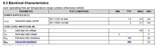
TIOS101: Power ration Input Pull Up Resistor (R_PU)
I am checking in to this value and will follow up shortly. Can I ask for more information about the application and why they need this value? Are they going to try to sink a lot of current out of this pin or drive this pin to a negative value that would result in a larger voltage drop and larger power dissipation that would be in a normal 3.3V or 5V application?
thanks for your quick response. The problem is more or less on the documentation side to get a stamp on our paperwork.
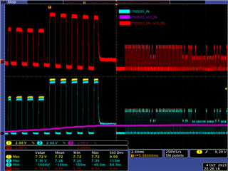
The TIOS101 is designed into a functional safety application. During production we have to parametrize a third party IC in-circuit. This IC is programmed by a bit sequence on its output port with partial higher signal level (~7,5V max., see record attached) than TIOS101 maximum ratings specify (Input IN, absolut max. rating = 6V). The Output of the IC is connected to Input IN of TIOS101 via a 10k resistor. TIOS101 is not supplied on VCC_IN during the process.
Measuring the input characteristics of TIOS101 Input IN shows a protection circuit to GND with ~11V breakthrough voltage. Is the input IN capable of taking this voltage level, in excess of specified maximum ratings, during manufacturing process? In normal operation the circuit operates at 5V level.
Thanks for the additional information about the application and question. I will have to check with the design team to verify the limits of the device. I will ask them and follow up with their response when I receive it. This may take a day or two, but I will ask them to try to provide a response by the end of the week.
I apologize for the delay and the design team is late in providing a response.
They did say that because the pullup/pulldown resistor is > 100k, this would NOT cause any electromigration concerns, but this does not addresses all potential risks that they need to evaluate.
I have reminded them again we are still waiting for their response and I will press them on the matter so that we can resolve this quickly.
I have followed up with the design team and they asked how long the programming will last, and at what temperature this will happen at so that they can get an accurate voltage/temp profile in their evaluation. I assume the programming is very quick, and that this will generally be at room temp (approximately 25C, but please confirm).
They also asked what the Rise/Falll time of the programming signal will be. If it is fast (i.e. 10nS) then we can run into issues with the ESD cells triggering at 7.2V. To avoid this we may need to slow the signal with a series resistor or small capacitor, etc. But I can't tell how fast those rise/fall times are from the scope plot. Can you confirm these times as well?
Our design team should be able to provide a voltage/temp profile that would be acceptable by Wednesday.
Ambient temperature during production: 20-30°C, Rise time min.= 2us, Typ.= 11us Max. time in excess of maximum voltage rating at input IN: 5ms (This occours several times during production in 100ms+x intervals)
Thanks for the information. Based on this, the feedback from our design team is:
The total duration should be less than 100ms, otherwise we would need to recalculate a new expected DPPM.
The minimum rise/fall time should be > 1uS so that the ESD cell doesn't trigger. If the rise/fall time is less than 1uS, there needs to be a 10k resistor in series with the IN pin to limit the current during programming.
It sounds like both of these criteria are met in the customer's situation, but I'm not sure how many intervals they will have for a single device that may cause the total 100mS duration to be exceeded.