This thread has been locked.

If you have a related question, please click the "Ask a related question" button in the top right corner. The newly created question will be automatically linked to this question.

DS90UB964-Q1EVM: Length count, Line count information in ALP.

Part Number: DS90UB964-Q1EVM
Other Parts Discussed in Thread: ALP

Hello Team,

Sorry for simple question.

pls understand that I have no way to verify this register 

My customer is using 913A and 964 for Surroud view.

they reported that ALP shows only PCLK but there is no information of Line length and line count in ALP info tap.

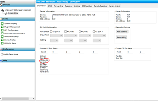
So Is there any register configuration needed to see those information??

I already confirmed their sensor send Hsync/Vsync to SER.

Thank you.

  • this is my script for bring up.

    913_964 bring up script.txt
    #913/964 bring up script
    devAddr = 0x7a
    serAddr = 0x30
    camAddr = 0x20
    
    serAlias0 = 0x34
    serAlias1 = 0x36
    serAlias2 = 0x38
    serAlias3 = 0x3a
    
    camAlias0 = 0x24
    camAlias1 = 0x26
    camAlias2 = 0x28
    camAlias3 = 0x2a
    
    #Deserialzer
    #Congigure LOCK signal on GPIO_0~3
    board.WriteReg(0x0F,0xF0) # Disable GPIO0~3 input mode
    board.WriteReg(0x10,0x81) # configure GPIO0 to bring out Lock for Port0
    board.WriteReg(0x11,0x85) # configure GPIO1 to bring out Lock for Port1
    board.WriteReg(0x12,0x89) # configure GPIO2 to bring out Lock for Port2
    board.WriteReg(0x13,0x8D) # configure GPIO3 to bring out Lock for Port3
    
    #CSI Port0 configuration
    board.WriteReg(0x32,0x01) # Select CSI port0 
    board.WriteReg(0x1f,0x02) # MIPI 800mbps output speed
    board.WriteReg(0x33,0x01) # enable CSI port CSI 4lane, CSI-2 non-continous clock mode
    board.WriteReg(0x21,0x01) # Enable Round robin forwarding to CSI0
    board.WriteReg(0x20,0x00) # forwarding of all RX input to CSI port0
    
    #RX Port0 configuration
    board.WriteReg(0x4c,0x01) # Congigure PORT_SEL to RX_PORT0
    board.WriteReg(0x58,0x58) # Enable Pass though and 2.5Mbps BCC speed.
    board.WriteReg(0x5c,serAlias0) # Alias SER_ID for Port 0
    board.WriteReg(0x5d,camAddr) # configure Cam_ID for Port0
    board.WriteReg(0x65,camAlias0) # Alias SER_ID for Port 0
    board.WriteReg(0x70,0x1f) # Assign RX0 data to VC-ID0 and Data Type YUV422 10bit
    board.WriteReg(0x6d,0x7f) # Configure RAW 10bit mode
    
    #RX Port1 configuration
    board.WriteReg(0x4c,0x12) # Congigure PORT_SEL to RX_PORT1
    board.WriteReg(0x58,0x58) # Enable Pass though and 2.5Mbps BCC speed.
    board.WriteReg(0x5c,serAlias1) # Alias SER_ID for Port 1
    board.WriteReg(0x5d,camAddr) # configure Cam_ID for Port1
    board.WriteReg(0x65,camAlias1) # Alias SER_ID for Port 1
    board.WriteReg(0x70,0x5f) # Assign RX1 data to VC-ID1 and Data Type YUV422 10bit
    board.WriteReg(0x6d,0x7f) # Configure RAW 10bit mode
    
    #RX Port2 configuration
    board.WriteReg(0x4c,0x24) # Congigure PORT_SEL to RX_PORT2
    board.WriteReg(0x58,0x58) # Enable Pass though and 2.5Mbps BCC speed.
    board.WriteReg(0x5c,serAlias2) # Alias SER_ID for Port 2
    board.WriteReg(0x5d,camAddr) # configure Cam_ID for Port2
    board.WriteReg(0x65,camAlias2) # Alias SER_ID for Port 2
    board.WriteReg(0x70,0x9f) # Assign RX2 data to VC-ID2 and Data Type YUV422 10bit
    board.WriteReg(0x6d,0x7f) # Configure RAW 10bit mode
    
    #RX Port3 configuration
    board.WriteReg(0x4c,0x38) # Congigure PORT_SEL to RX_PORT3
    board.WriteReg(0x58,0x58) # Enable Pass though and 2.5Mbps BCC speed.
    board.WriteReg(0x5c,serAlias3) # Alias SER_ID for Port 3
    board.WriteReg(0x5d,camAddr) # configure Cam_ID for Port3
    board.WriteReg(0x65,camAlias3) # Alias SER_ID for Port 3
    board.WriteReg(0x70,0xdf) # Assign RX3 data to VC-ID3 and Data Type YUV422 10bit
    board.WriteReg(0x6d,0x7f) # Configure RAW 10bit mode
    

    pls refer to attached when you answer my question.

    Thank you~!!

  • Hello Harry,

    I am not sure if I understood you correctly. Are you looking for registers where to read the Line length and line count on the UB964?

    If yes, these can be found in reg 0x73, 0x74, 0x75, 0x76

  • Hello Hamzeh,

    Thanks for your quick reply.

    Yes I also know this register.

    I got timing log in ALP by using this script

    .

    8547.913_964 bring up script.txt
    #913/964 bring up script
    devAddr = 0x7a
    serAddr = 0xb0
    
    
    serAlias0 = 0x34
    serAlias1 = 0x36
    serAlias2 = 0x38
    serAlias3 = 0x3a


    #Deserialzer
    #Congigure LOCK signal on GPIO_0~3
    board.WriteReg(0x0F,0xF0) # Disable GPIO0~3 input mode
    board.WriteReg(0x10,0x81) # configure GPIO0 to bring out Lock for Port0
    board.WriteReg(0x11,0x85) # configure GPIO1 to bring out Lock for Port1
    board.WriteReg(0x12,0x89) # configure GPIO2 to bring out Lock for Port2
    board.WriteReg(0x13,0x8D) # configure GPIO3 to bring out Lock for Port3
    
    #CSI Port0 configuration
    board.WriteReg(0x32,0x01) # Select CSI port0 
    board.WriteReg(0x1f,0x02) # MIPI 800mbps output speed
    board.WriteReg(0x33,0x01) # enable CSI port CSI 4lane, CSI-2 non-continous clock mode
    board.WriteReg(0x21,0x01) # Enable Round robin forwarding to CSI0
    board.WriteReg(0x20,0x00) # forwarding of all RX input to CSI port0
    
    #RX Port0 configuration
    board.WriteReg(0x4c,0x01) # Congigure PORT_SEL to RX_PORT0
    board.WriteReg(0x58,0x58) # Enable Pass though and 2.5Mbps BCC speed.
    board.WriteReg(0x5c,serAlias1) # Alias SER_ID for Port 0
    board.WriteReg(0x7c,0xe1) # configure low Vsync pol and use lower 8bit as valid input for Port0
    board.WriteReg(0xbc,0x70) # configure min time for FV to LV
    board.WriteReg(0x70,0x1f) # Assign RX0 data to VC-ID0 and Data Type YUV422 10bit
    board.WriteReg(0x6d,0x7f) # Configure RAW 10bit mode
    
    #RX Port1 configuration
    board.WriteReg(0x4c,0x12) # Congigure PORT_SEL to RX_PORT1
    board.WriteReg(0x58,0x58) # Enable Pass though and 2.5Mbps BCC speed.
    board.WriteReg(0x5c,serAlias1) # Alias SER_ID for Port 1
    board.WriteReg(0x7c,0xe1) # configure low Vsync pol and use lower 8bit as valid input for Port1
    board.WriteReg(0xbc,0x70) # configure min time for FV to LV
    board.WriteReg(0x70,0x5f) # Assign RX1 data to VC-ID1 and Data Type YUV422 10bit
    board.WriteReg(0x6d,0x7f) # Configure RAW 10bit mode
    
    #RX Port2 configuration
    board.WriteReg(0x4c,0x24) # Congigure PORT_SEL to RX_PORT2
    board.WriteReg(0x58,0x58) # Enable Pass though and 2.5Mbps BCC speed.
    board.WriteReg(0x5c,serAlias2) # Alias SER_ID for Port 2
    board.WriteReg(0x7c,0xe1) # configure low Vsync pol and use lower 8bit as valid input for Port2
    board.WriteReg(0xbc,0x70) # configure min time for FV to LV
    board.WriteReg(0x70,0x9f) # Assign RX2 data to VC-ID2 and Data Type YUV422 10bit
    board.WriteReg(0x6d,0x7f) # Configure RAW 10bit mode
    
    #RX Port3 configuration
    board.WriteReg(0x4c,0x38) # Congigure PORT_SEL to RX_PORT3
    board.WriteReg(0x58,0x58) # Enable Pass though and 2.5Mbps BCC speed.
    board.WriteReg(0x5c,serAlias3) # Alias SER_ID for Port 3
    board.WriteReg(0x7c,0xe1) # configure low Vsync pol and use lower 8bit as valid input for Port3
    board.WriteReg(0xbc,0x70) # configure min time for FV to LV
    board.WriteReg(0x70,0xdf) # Assign RX3 data to VC-ID3 and Data Type YUV422 10bit
    board.WriteReg(0x6d,0x7f) # Configure RAW 10bit mode
    

    After change FV polarity in 0x7c, I got timing information finally.

    I have 1 quick question here.

    now, image sensor input is 8bit RAW with 1280x944

    but I could see Horizontal : 2560byte and verital : 944.

    is this log correct? I think it should be 1280 because of color depth is 8bit RAW.

    Could you pls help me clarify this??

    Thanks

  • Hello Harry,

    may be the Imager is working in double-exposure mode?!

  • Double exposure???

    Now, I just remember that input PCLK from Imager is 94MHz but 964 side log in ALP shows it is 47Mhz.

    is this also related with double exposure??

    Thanks for your support all the time~

  • No, PCLK has nothing to do with double exposure. This is a settings on the Image sensor, which allows to send two pixels instead of one, one is short and the other is long.

    Please contact the Imager vendor and clarify.

  • Hello Hamzeh,

    Yes. I was told this information is wrong from camera company.

    Let me close this.

    Thanks for your support~