This thread has been locked.

If you have a related question, please click the "Ask a related question" button in the top right corner. The newly created question will be automatically linked to this question.

SN65HVD1477: Receiving Only Carriage Returns

Part Number: SN65HVD1477

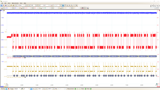
I have a SN65HVD1477 connected to a TI TIva microcontroller that I can't seem to receive data from. UART is being transmitted from Tiva microcontroller correctly, probing the D, and R pins of the SN65HVD1477 shows that data is being transmitted from the MCU correctly,

Tiva UART Data.csv

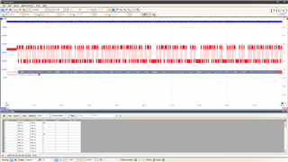
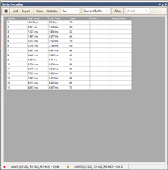
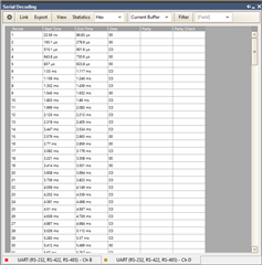
Data is being received by a DTech USB 2.0 to RS485 adapter,

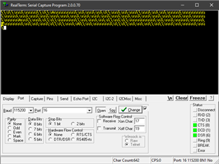
The data from the COM adapter is a bunch of carriage returns,

Has anyone experienced this problem?

Thanks,

Allan

  • Allan,

    So the communication is fine until the terminal tries to interpret it? Is it possible that noise from the COM adapter is corrupting the signal? If the R waveform from the RS485 transceiver to the COM adapter looks good, I'm not sure what else it could be.

    Regards,

    Eric Hackett

  • I suspect the baud rate is wrong. Try sending something from the PC, and compare the bit lengths in the waveforms.

  • The communication is fine on D until it goes through the SN65HVD1477. The differential output on Y and Z appears to mess up the UART data being transmitted. 

    Blue (R Pin), Red (D Pin), Gold (Y-Z Pins)

    Below is the UART data from Channel B (Red).

    Below is the UART data from the output,

  • The red and gold waveforms have the same shape. Nothing looks wrong.

    I do not know why your oscilloscope is not able to decode the differential signal. Try changing the threshold to zero.

    Check that the two +/- signals are not exchanged.

  • Clemens,

    You were right it was a baud rate problem. Although I am not sure why. The baud rate is somehow slower than what it is set to in the microcontroller.

    Thanks,

    Allan

  • For some reason removing this code from my project affects the buad rate of UART on A0, and A1,

     //==============    SSI     ==============
    
        //
        // The SSI0 peripheral must be enabled for use.
        //
        //SysCtlPeripheralEnable(SYSCTL_PERIPH_SSI1);
        //SysCtlPeripheralEnable(SYSCTL_PERIPH_GPIOB);
        //SysCtlPeripheralEnable(SYSCTL_PERIPH_GPIOE);
    
        //
        // Configure the pin muxing for SSI0 functions on port A2, A3, A4, and A5.
        // This step is not necessary if your part does not support pin muxing.
        // TODO: change this to select the port/pin you are using.
        //
        //GPIOPinConfigure(GPIO_PE4_SSI1XDAT0);
        //GPIOPinConfigure(GPIO_PE5_SSI1XDAT1);
        //GPIOPinConfigure(GPIO_PB5_SSI1CLK);
    
        //
        // Configure the GPIO settings for the SSI pins.  This function also gives
        // control of these pins to the SSI hardware.
        //
        //GPIOPinTypeSSI(GPIO_PORTE_BASE, GPIO_PIN_5 | GPIO_PIN_4);
        //GPIOPinTypeSSI(GPIO_PORTB_BASE, GPIO_PIN_5);
    
        //
        // Configure and enable the SSI port for SPI master mode.  Use SSI0,
        // system clock supply, idle clock level low and active low clock in
        // freescale SPI mode, master mode, 1MHz SSI frequency, and 8-bit data.
        // For SPI mode, you can set the polarity of the SSI clock when the SSI
        // unit is idle.  You can also configure what clock edge you want to
        // capture data on.  Please reference the datasheet for more information on
        // the different SPI modes.
        //
    //    uint32_t ui32SysClock = SysCtlClockFreqSet((SYSCTL_XTAL_25MHZ |
    //                                           SYSCTL_OSC_MAIN |
    //                                           SYSCTL_USE_OSC), 25000000);
    
    //    SSIConfigSetExpClk(SSI1_BASE, ui32SysClock, SSI_FRF_MOTO_MODE_0,
    //                           SSI_MODE_MASTER, 1000000, 8);
    
        //
        // Enable the SSI1 module.
        //
        //SSIEnable(SSI1_BASE);
    
        //Chip select pin.
    //    ROM_GPIOPinTypeGPIOOutput(GPIO_PORTL_BASE, GPIO_PIN_0);
    //    MAP_GPIOPadConfigSet(GPIO_PORTL_BASE, GPIO_PIN_0, GPIO_STRENGTH_12MA,
    //                                 GPIO_PIN_TYPE_STD);

  • Ask about that in the microcontrollers forum.

  • Thanks for the help here Clemens, as always. 

    JA,

    Let us know if there are any other questions related to the transceiver, otherwise I will be closing this thread.

    Regards,

    Eric Hackett