At present, when we use E-ELEMENTS' USB3 daughter board (including TI PHY: TUSB1310A) to debug, we find that the clock state output by phy is abnormal. The test situation and the questions to be consulted are summarized as follows:
Test situation: 1. Use E-ELEMENTS USB3_HT3 daughter board, use 40MHz crystal oscillator as the input clock of phy (TUSB1310A) on the daughter board;
2. Connect the pipe interface to the FPGA, the ULPI interface is left unconnected, and the JTAG signal is left unconnected;
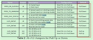
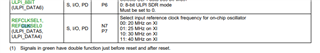
3. See the attachment for the default state of the strap pins configuration of phy;
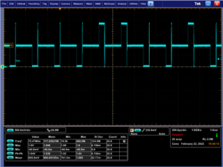
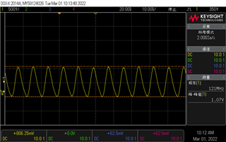
4. After the daughter board is powered on, configure the FPGA, the OUT_ENABLE signal of the output phy is always high, and the RESETN signal of the phy is released; 5. It is found that the PCLK output of phy is abnormal (see the attachment), and the ULPI_CLK is brought to the test point and observed to be 120MHz (see the attachment).
Question: 1. In the above test situation, is there any incorrect operation or control
2. If you only use the pipe interface of phy to test USB3, do you still need to use the ULPI interface to configure the internal registers of phy to achieve some initial states
3. In addition to the content mentioned in the above test situation, what are the necessary conditions for phy to work properly