This thread has been locked.

If you have a related question, please click the "Ask a related question" button in the top right corner. The newly created question will be automatically linked to this question.

DS90UB960-Q1: 953 960 can't link successfully when power up in -40 temp

Part Number: DS90UB960-Q1


Hi Team,

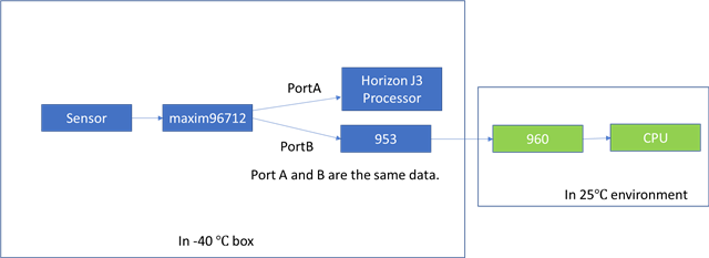
My customer now use 953+960. They could work normally in normal temp(25 ℃) but can't link successfully when power up in -40 ℃.

They now test 6* platform machine. All of their 953+960 can't link successfully when power up in -40 ℃

Here are the process they do:

1. Put the platform into -40 temp environment, wait 30 mins.

2. Power up this platform.

3. 953+960 status:

1) 960 Lock state is low. The I2C address of the 953 cannot be accessed, and the CRC status of the 960 is reported incorrectly
2) 960 Lock state is high. The I2C address of the 953 cannot be accessed, and the CRC status of the 960 reports an error
3) 960 Lock state is high. Can go to the I2C address of 953, 960 and 953 CRC status both report error
4) 960 Lock state is low. Can go to the I2C address of 953, TI960 and TI953 CRC status both report error
The above four phenomena are constantly changing. Phenomenon 1) has a higher probability and is in this state for a long time. Phenomenon 2 / 4 probability is low.

Could you kindly help for this?

  • Hi Amelie,

    Just to clarify, does the test involve placing the SER, DES, and cables all in the low temp -40 temperature environment?

    And if the system powers-up in the -40 temperature environment, is LOCK able to be established if the temperature rises?

    Are you able to run the MAP and provide the results in both the normal temp (25 degC) and low temp (-40 degC) environments? As temperature decreases, the margin should decline, but not fail completely. 

    Can you also measure the power supply rails to the 953 and 960 devices, at the pins of each device during the low temp condition? I want to make sure that the supplies are not dropping too low at a DC level or encountering excessive noise outside of the datasheet.

    Are you also able to provide the schematic and layout files as well (maybe by email since this is a public forum)? Our devices should meet the -40 to 105 degC specifications in the datasheet, if all of the channel requirements are met, which results from a combination of connections made and the PCB latout.

    Best,

    Justin Phan

  • Hi Justin,

    1. 953 in -40 box and 960 in 25 environment. So the issue is from 953. 960 is ok.

    2.Customer could try.

    3.can't do this. Because in -40, can't find 953 I2C address. And in -40, 96712 and J3 work normally. So the data from 96712 (port A and B) are ok.

    4.Power are ok in 953 and timing are also ok in 953.

    5. SCH:

    One more question is what the meaning of 0x1D? Does it means when temp is under -40, 953 will alert to 960?

    Customer really want to know whether this 0x1D will effect the abnormal work in 953. Whether need to do something for this register.

     What does this code use?

    Here are the register in -40

    Here are the register in environment temp.

  • Hi Amelie,

    I will review the materials posted. But here are some of my initial responses:

    1. On the DOUT+/- pins of the UB953, do the AC coupling capacitors match the ones used on the RIN+/- pins in the connected UB960 deserializer?
    2. Is there a PoC network used on the UB953 board? If so, could you post it so that I can see?
    3. Some of the information is missing in the schematic. Can you provide the connections for the IDX, MODE, and PDB pins? 
    4. Also, the LPF1 connection is wrong. LPF1 must be connected to VDDPLL using a 22nF AC coupling capacitor, as defined in the datasheet, in order to minimize noise on the PLLs and ensure the PLLs perform at a high performance. See Section 8.2.2.4 Loop Filter Decoupling in the UB953 for more details.

    Do you have a full schematic, which shows all of the connections made to the UB953? I'd like to do a more thorough review.

    And for your customer question, the programming example that uses register 0x1D is used to configure the voltage/temperature alarm on the UB953. The UB953 can send diagnostics information to the connected deserializer and also trigger interrupts. You can set a lower/upper threshold for each voltage/temperature sensor on the UB953 and then have it trigger an alarm bit in the connected deserializer, once the set thresholds are exceeded. This bit doesn't really affect the normal operation of the Ser/Des pairing, except triggering an interrupt on the connected deserializer. It shouldn't be the cause of the issue.

    More details can be found in the deserializer's datasheet, but here is a quick excerpt from the UB960 datasheet:

    Best,

    Justin Phan

    • On the DOUT+/- pins of the UB953, do the AC coupling capacitors match the ones used on the RIN+/- pins in the connected UB960 deserializer?

    The AC cap of UB953 and UB960 are both 33nf.

    • Is there a PoC network used on the UB953 board? If so, could you post it so that I can see?

    Customer don't use POC to supply and 960/953 have their own supply circuit.

    Some of the information is missing in the schematic. Can you provide the connections for the IDX, MODE, and PDB pins?

    FYI as following

    Also, the LPF1 connection is wrong. LPF1 must be connected to VDDPLL using a 22nF AC coupling capacitor, as defined in the datasheet, in order to minimize noise on the PLLs and ensure the PLLs perform at a high performance. See Section 8.2.2.4 Loop Filter Decoupling in the UB953 for more details.

    LFP1 already have 22nf to VDDPLL and no problem

  • Hi Amelie,

    On the PDB pin, I see a a 10-kOhm pull-up resistor and a 100nF capacitor to ground. However, the capacitor needs to be >=10uF, as specified in the datasheet. Could the customer replace that capacitor to the appropriate value and see if that resolves the issue?

    On the I2C_SCL and I2C_SDA lines, could the customer also measure the I2C bus capacitance on the UB953 and then use App Note SLVA689 to calculate the optimal pull-up resistor value for their system?

    Best,

    Justin Phan

  • Hi Justin,

    For PDB and I2C, customer already fixed now and tested again. But still can't work in -40 temp... Any other advice?

    May I ask whether they could change EQ value so as to make it pass in -40?

  • Hi Amelie,

    After the customer has changed the capacitor on the PDB pin to be >=10uF, are they able to send I2C commands to the UB953? If the PDB pin has the correct pull-up resistor and decoupling capacitor, then it should be possible to access the UB953 I2C address.

    Also, the power rails need to be within spec at the lower temperature. You previously mentioned that power and timing are okay. Could the customer provide the probing of the Power-Up Sequence at -40 deg C, so that I can confirm?

    My initial thoughts were that the power rails might not be stable across full temp range, and low temp causing instability and lock issues. It might also be good to check the type of bypass capacitors used, and if they are choosing the correct temp class based on their requirements (X7R vs. Y5V for example). 

    If the UB953 device has the proper power-up sequence and can be accessed via remote I2C, I recommend using the MAP tool, which was designed to optimize the AEQ settings and can help LOCK time and link robustness. See this document for more details: https://www.ti.com/lit/ug/snlu243/snlu243.pdf 

    Best,

    Justin Phan