This thread has been locked.

If you have a related question, please click the "Ask a related question" button in the top right corner. The newly created question will be automatically linked to this question.

SN65HVD3082E: SN65HVD3082E

Part Number: SN65HVD3082E

Hello,

About 4 months ago I stated our problem about the manufacturer using SN65HVD3082ED instead of SN65HVD72DR in the below linked thread

https://e2e.ti.com/support/interface-group/interface/f/interface-forum/1054139/sn65hvd72-about-vp3082-marking-code/3904043#3904043

If I need to give more details about our product, the product is a thermostat and there is two different modes which are steady-state mode and normal operation mode. If the device is in steady-state mode before power restart, it starts on steady-state mode. But if the device is on normal operation mode before power restart, it starts in normal operation mode. On steady-state mode the device just shows the temperature on the display and turns off the fancoil controls. 

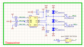
To summarize a customer of us made a complaint about our products saying they are not communicating. After examining the products we have in the warehouse, we realized  our manufacturer have been using SN65HVD3082ED instead of SN65HVD72DR. The problem is on the datasheet of SN65HVD3082ED it is stated that the IC should be supplied by 5V. But our circuit design have been supplied by 3.3V (You can see circuit design at the attachment). So naturally we thought the problem is caused by the wrong supplying voltage. After that we tried to do tests in the office environment.. As we discussed in the other thread linked above after adding 36 device in the line the communication fails, there is no problem here. But our customer said even if there is  15 devices in the line the communication fails. 

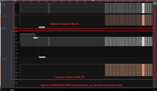
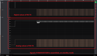
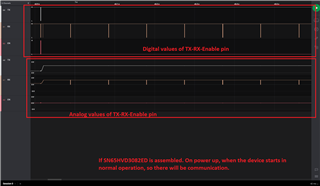
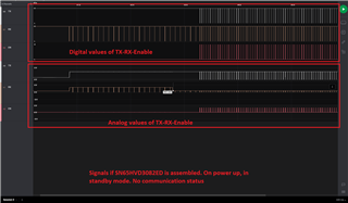
After our customer feedback one of our field engineers visited the field and saw that if the device starts working in steady-state mode there would be no communication and if the device started to working in normal operation mode there would be no problem in the communication. The field engineer brought one of the devices so we examined it.

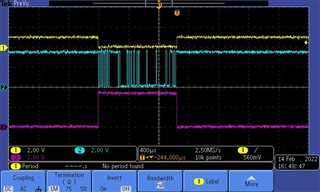
We examined the product brought from the field communicating with it peer to peer. As you can see in the attached images (yellow-receive signal, blue-transmit signal, pink-enable signal) the signals are peculiar. When there is no communication, receive signal voltage level starts 3.3V voltage level but after 1 second drops around 1V and it seems this is the reason why the communication fails. Even if there is a data, since the voltage level is around 1V MCU can not identify it as a data and starts sending a garbage data. You can see there is no problem with transmit data voltage level. 

We can not see this problem when testing the products we have in the warehouse so we thought the products being damaged in the field. But we can not understand the situation. Why would there be no problem if the device starts on normal operation mode but just when it starts on steady state mode? Is this even possible for the IC to behave differently when there is no change in the supply voltage? 

I wanted to fully explain the situation, sorry for the long explanation.

 Note: The baudrate is 76800kbps.

  • Hi Nihan,

    To clarify I have a few questions:

    1. What are the scope shots - as it what does the left side represent and is the right side a picture of. Is this measuring one device at the R, D, and enable pins or is there more than one device that is being shown.

    2. Are the scope shots from only devices that are potentially damaged?

    3. Are the HVD72 devices the ones in the test scope shots - I just want to clarify as it still states that part in the schematic.

    4. What conditions is the device under when it power's on in steady state mode (voltages on devices pins at startup) - same question for normal operation mode. 

    If you could just add scope shots of the bad device compared to a good one it will be a good indication of what could be happening in the device. Beyond that from the initial information that you have provided since this problem is seen in one condition and not the other that would make me first want to look at what differences does the transceiver see under the two modes of operation at startup. The dip in the R voltage when enable goes high could also indicate internal damage somewhere inside the part. If you could confirm the questions I can look a bit deeper into what could have caused damage and if that make sense for what is being seen. 

    Please let me know so I can dig a bit deeper to see what could be happening!

    Best,

    Parker Dodson

  • Hello Parker,

    1.The first picture is our signals when there is no communication. The second one is belong to when there is a communication.  (yellow-receive signal, blue-transmit signal, pink-enable signal)

    2.Yes, they are from the potentially damaged devices. But not damaged products which are in our warehouse behave same as the second one. I know it is strange since there is a little voltage drop on the receive signal. But since it is still in the range of high voltage level there is no problem, MCU still understand it. 

    3.There is HVD72DR on schematic but on the pcb SN65HVD3082ED is assembled, because our manufacturer thought they are equivalent and assembled without asking us. At the attachment of this post you can find the behaviour of HVD72DR  assembled product on normal operation mode and steady-state mode (actually it is standby mode) 


    4. You can find the shots we took at the time of power up below for normal operation mode and standby mode of the product. For both situations power voltage of the communication IC is 3.3V and stable. 


    When the damaged IC works (on normal operation mode) sometime after startup the signals are like below

    You can see dip voltages of R signals on the images. 

    I hope I answered all your questions. Waiting for your reply.

    Thanks in advance. 

  • Hi Nihan,

    Thanks for the detailed follow up I really do appreciate it!

    That being said - it does seem that there is some electrical issue seen when the DE signal goes high - it seems to be dropping a voltage - probably over the pull-up resistor since the drop is similar in both cases (this makes me think that there is about a  100uA current being pulled on the R pin when DE goes high. Every pin is internally connected to VCC and ground - so there could be internal damage causing this current draw as when the RE pin is low the R output should be high-z when connected to VCC should put it ~3.3V. In the cases where communication fails - it seems that the R pin has a 1V signal on it - do you know where this coming from? Because it could also indicate that the device is shunting more current when starting in steady state mode. 

    However I do suspect there is damage on the device - and while it does seem the damage has something to do with the R pin shunting current to ground - this could indicate issues with multiple pathways within the device. I do suggest the next steps in this problem are to look at our failure analysis page:
    https://www.ti.com/support-quality/additional-information/failure-analysis.html

    It has some steps on how to move forward with these issues and gives a chance for our quality team to look over it - they may want to test bad units or do an FA - it depends a few factors that they would be better to explain; however there help can be utilized here to see what next steps might need to be taken to help uncover the root of the problem. What I will say about the current schematic - I don't see a lot of "risk" of damage for normal operation - however that doesn't discount other more "transient events" that could cause damage. What that would be depends on the damage seen on the part and where the actual damage lies - but it does seem R is shunting current and the R voltage value when starting in steady state seems too low for a port that should be hi-z. 

    Please let  me know if you have any other questions and I will see what I can do!

    Best,

    Parker Dodson 

  • Hello Parker,

    After receiving your reply we tried to find the reason of the current beign pulled as you told.

    I'm not sure if I mentioned this but we are communicating using bacnet. So we tried to if there is any communication problem if we use modbus protocol. We realized that there is no problem with communication either on normal operation mode or steady-state mode. But while checking signal voltage on modbus communication, we realized that voltage levels are normal and on ~3.3V level. There is no voltage drop to ~2.6V level on R pin like it happened on working communication status of HVD72DR or SN65HVD3082ED (You can see images belong to this situation in the post I last sent)

    After realizing that we compared Uart Init function of modbus and bacnet firmwares. In the modbus communication firmware, receive signal was defined as a floating pin. But in bacnet communication firmware it was defined as alternative function push-pull pin. So using damaged ICs we changed bacnet firmware uart init function receive pin definition to floating pin and this worked. There is no voltage drop either on normal operation mode or steady-state mode. Do you have any knowledge about this? If you can please enlighten us about this.
    We are also curious if this alternative function fush-pull definition is the cause of the damage on these ICs. We have been using this definitions for our Bacnet communication devices for years but after so long we received the complaint about communication. We are waiting for your comment about the reason.

    Best Regards.

  • What I will say about the current schematic - I don't see a lot of "risk" of damage for normal operation - however that doesn't discount other more "transient events" that could cause damage. What that would be depends on the damage seen on the part and where the actual damage lies - but it does seem R is shunting current and the R voltage value when starting in steady state seems too low for a port that should be hi-z. 

    I also would like to know more details of your thoughts about the protection of the circuit design. We placed TVS diodes to prevent transient voltages. Is this not enough? Would you suggest any other protection to prevent transient voltages and noise?

  • Hi Nihan,

    For the protection circuits:

    1. The issue seems to be at the R pin - so I doubt damage is from the A/B pins (as these pins are already the most robust pins on the device in terms of their ratings anyway) The TVS diodes added should keep any damaging signals at bay in most scenarios - so I don't think there is a major issue there. The logic pins are the most susceptible to damage as the pins only are rated from -0.3V to VCC + 0.3V so a transient spike could potentially cause issues. 

    For the firmware issue:

    From what I could find this could be the issue - and it may not be device damage. Could you clarify if the BACNET is programmed in an output push pull configuration when the failure occurs? if it is this could cause failure - not due to the transceiver but due to the GPIO pin state. This pin should be programmed to be either floating (which when you did this its fixes this problem - leading me to believe this could be a firmware error) or as an input push push configuration. Since it does seem there could also be that voltage drop on the HVD72 device that you tested - but it just doesn't cause the same issues as the device that is actually on the board. 

    A few quick tests to try to see if it is independent of the transceiver is too: 

    1.  Remove the transceiver (these inputs are high impedance so leaving them floating shouldn't be a huge issue for the test) and apply the same signals you normally would apply.  If the R voltage dips when configured in the push pull configuration then this voltage drop is from firmware.

    2. Configure the Device in an input Push Pull Configuration (if the device allows for this configuration) - if communication works again this confirms that it is a firmware issue.

    Please let me know if these tests result in results that possibly show the issue is independent of the transceiver. If it does it may just be as simple as changing the startup function to floating if possible to prevent this error with this device.

    Best,

    Parker Dodson