This thread has been locked.

If you have a related question, please click the "Ask a related question" button in the top right corner. The newly created question will be automatically linked to this question.

TCA9406: Higher rise time with the driver than without the driver.

Part Number: TCA9406
Other Parts Discussed in Thread: TCA9517, TCA9800

Hi,

I am currently facing a problem with the TCA9406 driver that I use as an SMBus driver to communicate with a battery.

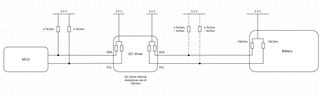
I attach the layout of the SMBus to this message. On the schematic, one of the pairs of pull-up resistors is displayed with a dotted line. For these resistors, I have made some test without them, with some of 4.7kOhms and with another pair of 1kOhm each.

When communicating over the SMBus with the battery, we measure weird noise in the signal of both data lines.In order to show the difference, I measured the clock before the driver and after the driver. I also attach them to this message. As you can see, the rising time of the clock before the driver is much better than the one after the driver. By reading the datasheet I understood that the rise time is accelerated on the second part of the rise as the output resistance of the driver is decreased to approximately 50Ohms. This acceleration of the rise seems to introduce a spike in the voltage of the line.

SMBus_clock_measurements.pdf

I used additional pull-up resistors to reduce the rising time of the lines between the driver and the battery. I have made some tests without them, with resistors of 4.7kOhm and 1kOhm. The tests without the resistors and with the 4.7kOhm resistors gave a result similar to the one presented in the PDF document. The tests with the 1kOhm resistors was unsuccessful as the equivalent pull-up resistance was too low and the voltage of the logic zero of the slave was too high and was not considered as a logic zero by the master anymore.

The communication is done at 50 kHz and should not be too quick for the TCA9406 as it is supposed to work for up to 1 MHz.

  • Apparently, the edge accelerator times too early. This happens when the capacitance is too high. How long are the traces? Are there any connectors or cables?

    What is the purpose of the TCA9406 in this circuit? It is not used as a level shifter, and it is not a buffer.

  • Hi Felix,

    What are you trying to achieve with the TCA9406? You are not level translating since both sides are pulled up to 3.3V and this device is not buffer so you cannot isolate both sides of your bus during operation. Are you looking for a buffer?

    Do you know what the capacitive load on your bus is? Slow rise times are usually due to high capacitive loads.

    Can you also provide a scope shot of one zoomed in rise time on the clock signal? The one shots in the device will turn on for approximately 30 ns and I want to see if it is working correctly.

    Best,

    Chris

  • Hi Clemens,

    Thank you for your answer. We have measured the lines after removing the I2C driver and the rise time seems reasonable and without any artifacts. I attach you one of these measures. As a side note, the following measure as been done with a frequency of 100kHz, so with a frequency twice as high as the one with the driver.

     SMBus_no_driver_measurements.pdf

    For that reason, we believe that neither the traces nor the connector we use for the battery are the source of the possible capacitance, but that the driver may be the cause of it. Do you think it could be an explanation?

    We are mainly using this driver to protect the PCB from electrostatic discharge and to increase the driving power of the lines.

    Thank you for your support!

  • Hello Chris,

    Thank you for replying to my question.

    We are currently using the driver to increase the protection of the PCB against electrostatic discharges and to increase the driving power of the SMBus lines.

    I don't know the capacitive load of the bus. However, we have made some measurements of the communication after removing the driver from the PCB and the signal seems much cleaner. I attach you one of the measurements made under that configuration. These measurements have been made with a frequency of 100kHz, so twice as high as the one with the driver, and the signal seems to be fine.

    7144.SMBus_no_driver_measurements.pdf

    Do you think the driver could be a source of capacitance?

    Please find attached a zoom-in of the rising edge of the clocks.

    SMBus_clocks_zoomed-in_rising_edge.pdf

    Thank you for your help!

  • The TCA9406 is a passive switch and has zero DC driver power.

    To buffer the I²C signals, use a device like the TCA9800 or TCA9517.

  • Thank you very much!

  • Felix,

    I am going to close the thread since it sounds like you are going with another device.

    Best,

    Chris