This thread has been locked.

If you have a related question, please click the "Ask a related question" button in the top right corner. The newly created question will be automatically linked to this question.

TPD4E02B04: 10Gbps PoE PSE Injector

Part Number: TPD4E02B04
Other Parts Discussed in Thread: TPD1E01B04, , ESD401, TPD4E1B06, BOOST-PSEMTHR-007, ESDS304

Hi All,

I'm looking for a ESD and Surge protection (on data lanes) recommendation for 10Gbps PoE PSE Injector ( there is no ETH phy on the device but only magnetics to inject the power)

My configuration is RJ45 (Data Input) -> Magnetics -> RJ45 ( Data output + PoE)

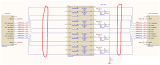
Q1)Do you recommend ESD devices ( TPD1E01B04, TPD4E02B04 or ESD401, TPD4E1B06)  on data lanes on the marketed positions in picture below?

Q2) Eg what is the difference between ESD401 and RClamp0524S ( this one can be used between RJ45 and magnetics in PoE as per DS) ? Booth have Reverse stand-off voltage 5V?

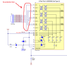
Q3)on BOOST-PSEMTHR-007 ( no ESD protection on data lanes)  the MDCT pins are no connect why is that so? don't they need decoupling caps and BoB Smith termination? ( Pin 12,6,1,7)

https://e2e.ti.com/support/tools/simulation-hardware-system-design-tools-group/sim-hw-system-design/f/simulation-hardware-system-design-tools-forum/1105095/tida-01411-10gbps-poe-pse-injector

Best Regards,

David.

  • Hi David,

    Please see my answers to your question below:

    Q1.) Out of the list you gave, ESD401 would work the best. However, the best device in our portfolio for this application would be ESDS304. 

    Q2.) RClamp0524S is a line-to-line surge protection device. Notice that there is no GND pin. This is used to clamp differential surges. The device will only start conducting if the voltage between the two line exceeds 5 V. The same functionality can be achieved with ESDS304 by simply floating the GND pin.

    Q3.) It looks like this was answered in the E2E post you linked at the end of this post. 

    For more info about ethernet protection, please read this app note: https://www.ti.com/lit/an/slvae50a/slvae50a.pdf?ts=1654013064313 

    Regards,

    Matt Smith 

  • Hi Matt,

    thank you for the replay and the AppNote.

    After learning more about the diodes, all that i proposed and also the ESDS304 are suggested at the PHY side.

    As we are doing PSE injector we don't have a PHY but only the magnetics transformer ( one side is data input port and the other side is PoE + data output port)

    The PoE center tap pins will be protected with MOV, but what about the data lanes.

    I'm asking my self does it even need protection, because there is no PHY to protect.? The data input lanes will be passed to the data output lanes via transformer?

    If yes, Do you recommend the ESDS304 also on the PoE ? ( in the DS of ESDS304 the diodes are used on the PHY side and not CABLE side)

    Best Regards,

    David.

  • Hi David,

    Understood. If the data lanes are just passive and not connected to any ICs in the system, then protection diodes might not be necessary. The only use case I see for protection diodes on the data lines in this system is if they are routed closely to other sensitive lines that are not protected from surge or ESD. During a surge or ESD event on the data line, the energy could couple over to the unprotected line and potentially damage the downstream circuitry it is connected to. A good rule of thumb is to protect every line that is exposed to the outside world to ensure robust system-level protection. Please refer to the screenshot below from our ESD Packaging and Layout Guide for more details:

    Regards,

    Matt 

  • Hi Matt,

    thanks for the update. so i should have enough clearance to avoid strong coupling.

    Nevertheless if i add the ESD diodes on the data lanes what is the right way:

    1) So if i want to do a differential protection on data lanes i can use ESDS304 with GND pin floating, and connect it between tow signals in one lane.

    on the data side (left side in picture) i can use is because is only ethernet, can i also use it on the PoE side data lanes (right side in the picture) ?

    2) How can i do common mode protection? Connection one side of EDSD304 to data  signal and one side to SHIELD?

    Best Regards,

    David.

  • Hi David,

    Let me explain in terms of an Ethernet setup with a PHY since that is the most common scenario and easier to explain. In your case, when I say "PHY side of the transformer", I'm referring to the left, data side of your system and "connector side of the transformer" will be referring to the right, PoE side of your system. 

    You would only need to float the GND pin of ESDS304 if you are placing it on the connector side of the transformer since that side is prone to high common-mode voltages, especially during PoE, that exceed the breakdown voltage of the diode and cause it to prematurely conduct during normal operation. Floating the GND pin makes it to where only an excessive differential voltage between 2 signal lines will cause the diode to conduct, not the voltage from a signal line to ground. For example, if a differential surge happens on D1+, the voltage difference between D1+ and D1- exceeds the breakdown voltage of the diode, and the diode clamps the voltage to D1-. This will equalize the voltage between the 2 lines and turn the differential surge into a common-mode surge, which will be blocked by the transformer. However, the best way to utilize ESDS304 is to place it on the PHY side of the transformer with the GND pin connected. This way, you allow the transformer to protect the system to its full capability and are not limited by the current rating of the diode. The transformer will take care of any common mode surges, and any residual differential surges that pass through the transformer will be shunted to ground by the ESDS304. You essentially have 2 lines of defense to protect the PHY with this method. 

    The only time you would really need an additional protection device for common-mode surges on the connector side is if the surge current exceeds the surge rating of the transformer. These device would need to have a working voltage greater than the PoE voltage which is usually >50 V. However, using connector side devices like this will require PHY-side protection. This is because during a common-mode surge, one of the connector side devices will conduct before the other, creating a secondary, differential surge that can bypass the transformer and damage the PHY. 

    I hope my explanation was clear and answered your questions. Please let me know if you need any clarification on anything.

    Regards,

    Matt