This thread has been locked.

If you have a related question, please click the "Ask a related question" button in the top right corner. The newly created question will be automatically linked to this question.

SN65HVD1050: Circuit review and suggestions

Part Number: SN65HVD1050


Hi,

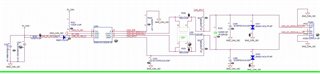
We design SN65HVD1050 for CAN bus Circuit, please help review this circuit is correct.

Looking forward to your advise. Thank you.

Willy.

  • Hi Willy,

    This schematic looks good. I don’t have any changes to recommend.

    Do you know why the customer is interested in using SN65HVD1050 instead of a newer 8-pin CAN transceiver like TCAN1044A? Newer devices have improved performance and are often the most cost competitive for the same feature set. TCAN1044A will also have the best long term supply capability of our 8-pin CAN IC's, so it may be worth considering the use of this device over SN65HVD1050. 

    Let me know if there are any questions or concerns regarding the design. See my notes below. 

    • Decoupling capacitors included and valued appropriately.
    • Split capacitor and IC connections included; values not shown.
    • Bus capacitors included; valued not shown - ensure placement close to connector and along signal path.
    • TVS diode included - ensure placement close to connector and along signal path.
    • Termination resistors included correctly and valued appropriately.
    • Optional CMC placed nominally between transceiver and termination.
    • All pull-up / series resistances are acceptable.

    Regards,
    Eric Schott

  • Hi Eric,

    Thanks for reply,

    I have new one question for CAN bus PCB trace impedance. SN65HVD1050 datasheet not found this data.

    Do we need to control impedance of the CAN BUS traces ?
    If yes what is the impedance value ?
    Can CAN BUS signal traces affect to memory layout if I didn't control CAN BUS trace impedance ?

    We design Circuit net name as below
    CAN_TX_ISO, CAN_RX_ISO need impedance control?
    CAN_DC_MODULE_H, CAN_DC_MODULE_L need impedance control?

    Example: The USB trace width and spacing of the DP and DN signals must meet the differential impedance requirement of 90 Ω

    Looking forward to your advise. Thank you.

    Willy.

  • Hi Willy,

    Good question here. 

    Impedance matching helps analog signals by reducing the impedance mismatch seen by the signal as it travels along its path. This helps reduce signal reflections and oscillations which are considerable factors in large, complex, or very high speed networks. The primary means for reducing these reflections is the inclusion of termination resistance at the end of the network. The value of the termination resistor should match the characteristic impedance of the cable. Typical impedance for CAN is 120-ohms. 

    For impedance matching of PCB traces, there are a few things to consider for CAN. First of all, choosing not to match the impedance of the cable will indeed help reduce reflections, but this is only marginally beneficial as the transition speeds for CAN are relatively slow. Generally the more significant aspect to consider for CAN is the expected current through the PCB lines. Because CAN is a fault tolerant interface that is able to withstand faults to GND or battery and experience a relatively harsh ESD and EMC environment, the PCB traces should also support the currents produced by such conditions. This requires thick PCB traces with low series resistances relative to high speed digital signal lines. 

    For this reason, it is common for designers to forego perfect 120-ohm impedance matching on PCB traces to ensure fault tolerance of the board as a whole. For high-speed applications with large or complex networks where signal integrity is already more strained may choose instead to value the PCB impedance and provide less tolerance for high-current fault cases. 

    The digital TXD and RXD pins are relatively low-speed signal lines (5Mbps max for CAN FD). Therefore, they can be treated as medium-speed signal lines and impedance control is not critical. Some applications choose to include series resistors around 10-ohm to 33-ohm to limit the current through these signal lines, though this is not required. 

    Let me know if you have any more questions.

    Regards,
    Eric Schott