


Hi Team,
I am supporting a USB3.x design - and there are some generic routing questions I am trying to answer.
I am referencing this literature for design info: https://www.ti.com/lit/an/spraar7i/spraar7i.pdf
In a multi-layer board design, I know you set the Layer Stackup based on characteristics from the board house, and use this to calculate the width/spacing of traces to achieve a target differential impedance.
[1] Which of the following routing techniques would be better?
- SuperSpeed traces on Layer #1, and a clean Reference GND on Layer #2
- SuperSpeed traces on Layer #1, and voiding under/around the traces (no copper reference GND) for 2-Layers deep; instead using Layer #1 GND pour around the traces for the Reference Path?
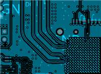
Below image shows Layer #1 with the voiding on Layer #2 and Layer #3; Reference GND is copper pour around the traces; GND "stubbing" is observed...

[2] Which of the following trace-length matching techniques is the best for cleaner signals?
- Use sawtooth serpentine routing (45deg angled sawtooth bends) to match length of shorter trace to the longer trace
- Use accordion serpentine routing (rounded "squiggly" bends) to match length of shorter trace to the longer trace
[3] Where would you want to place the trace-length matching routing? (Assuming a basic connector / hub or SoC connection)
Also, let's say there is some small length mismatch around the ESD/Choke devices, but the largest mismatch is at the Hub/SoC
- Put the trace-matching routing as close to the "most" mismatched section -> usually at the SoC
- Put the trace-matching routing spread out over the trace here and there, wherever the lengths try to deviate
- Put the trace-matching routing closer to the Driver of the Tx signal? Or the Receiver of the Tx signal?
- Since all we are doing is matching lengths to keep edge timings sync'd, we don't care; in the middle of the trace somewhere is fine
[4] Any thoughts on Common-Mode Filters designed for PCIe or USB3? Good/Bad?
I know there are so many other techniques described in the above literature, but I have seen reference designs doing different things and would appreciate a second opinion from the USB team.
Regards,
Darren
