This thread has been locked.

If you have a related question, please click the "Ask a related question" button in the top right corner. The newly created question will be automatically linked to this question.

DS90UB954-Q1: CSI SOT signal's not correct on timing and level while generating color bar pattern

Part Number: DS90UB954-Q1

Hi,

I'm working on a case and generating color bar on TI DS90UB954, and passing through CSI-2x4lanes to a SOC.

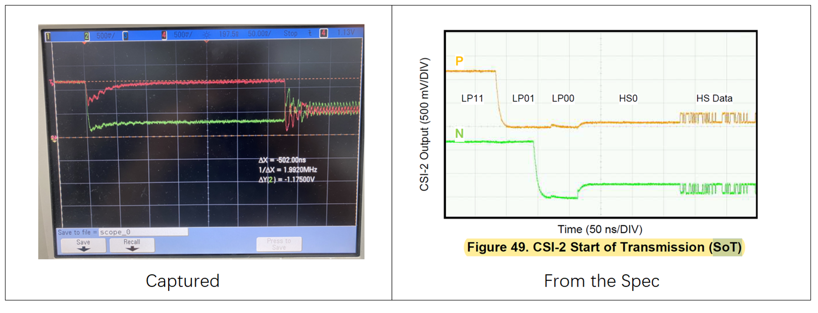
Since the SOC can not detect the SOT, I get the below capture from one of the data lane pairs. (Actually all 4lanes look the same.)

I can see it's way different from the 954 spec, but having no idea what I'm doing wrong.

I've checked the power supplies and they look correct.

Can you help to give some advice on what's the possible cause or what should I do? Thanks,

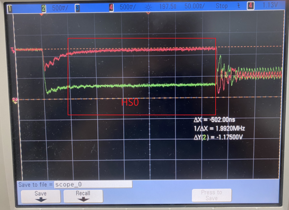
And while I'm changing the CSI0_THS_ZERO register, below part is changing and that points out the HS0 field. But when I'm changing other time related registers of CSI0, nothing happen.

Thank you!

  • Hello,

    The UB954 follows standard CSI-2 protocol, so the figures in the datasheet provide a brief overview of how the data transitions would look like in a standard CSI-2 receiver/transmitter.

     Are you using the built-in PATGEN feature in the UB954 device to generate the color bar test pattern?

    Here is an example script that can be run on the UB954 device to enable the PATGEN feature and have the device output data at an example resolution over 4 data lanes:

    954_CSI_patgen_RAW12_1920x1080p30.py
    """
      Copyright 2018 Texas Instruments Incorporated. All rights reserved.
    
      IMPORTANT: Your use of this Software is limited to those specific rights
      granted under the terms of a software license agreement between the user who
      downloaded the software, his/her employer (which must be your employer) and
      Texas Instruments Incorporated (the "License"). You may not use this Software
      unless you agree to abide by the terms of the License. The License limits your
      use, and you acknowledge, that the Software may not be modified, copied or
      distributed unless embedded on a Texas Instruments microcontroller which is
      integrated into your product. Other than for the foregoing purpose, you may
      not use, reproduce, copy, prepare derivative works of, modify, distribute,
      perform, display or sell this Software and/or its documentation for any
      purpose.
    
      YOU FURTHER ACKNOWLEDGE AND AGREE THAT THE SOFTWARE AND DOCUMENTATION ARE
      PROVIDED AS IS WITHOUT WARRANTY OF ANY KIND, EITHER EXPRESS OR IMPLIED,
      INCLUDING WITHOUT LIMITATION, ANY WARRANTY OF MERCHANTABILITY, TITLE,
      NON-INFRINGEMENT AND FITNESS FOR A PARTICULAR PURPOSE. IN NO EVENT SHALL TEXAS
      INSTRUMENTS OR ITS LICENSORS BE LIABLE OR OBLIGATED UNDER CONTRACT,
      NEGLIGENCE, STRICT LIABILITY, CONTRIBUTION, BREACH OF WARRANTY, OR OTHER LEGAL
      EQUITABLE THEORY ANY DIRECT OR INDIRECT DAMAGES OR EXPENSES INCLUDING BUT NOT
      LIMITED TO ANY INCIDENTAL, SPECIAL, INDIRECT, PUNITIVE OR CONSEQUENTIAL
      DAMAGES, LOST PROFITS OR LOST DATA, COST OF PROCUREMENT OF SUBSTITUTE GOODS,
      TECHNOLOGY, SERVICES, OR ANY CLAIMS BY THIRD PARTIES (INCLUDING BUT NOT
      LIMITED TO ANY DEFENSE THEREOF), OR OTHER SIMILAR COSTS.
    
      Should you have any questions regarding your right to use this Software,
      contact Texas Instruments Incorporated at www.TI.com.
    
    """
    # CSI patgen                 
    # Python script CSI_patgen_RAW12_1920x1080p30
    # Version 0.91   
      
    # CSI cont clk and CSI enable                           
    # board.WriteReg(0x32, 0x01)                            
    board.WriteReg(0x33, 0x03)                
     
    board.WriteReg(0xB0, 0x02)                # IA_AUTO_INC=1
    board.WriteReg(0xB1, 0x01)                # PGEN_CTL
    
    board.WriteReg(0xB2, 0x01)                # PGEN_ENABLE=1
    board.WriteReg(0xB2, 0x33)                # PGEN_CFG
    board.WriteReg(0xB2, 0x2C)                # PGEN_CSI_DI
    board.WriteReg(0xB2, 0x0B)                # PGEN_LINE_SIZE1
    board.WriteReg(0xB2, 0x40)                # PGEN_LINE_SIZE0
    board.WriteReg(0xB2, 0x01)                # PGEN_BAR_SIZE1
    board.WriteReg(0xB2, 0x68)                # PGEN_BAR_SIZE0
    board.WriteReg(0xB2, 0x04)                # PGEN_ACT_LPF1
    board.WriteReg(0xB2, 0x38)                # PGEN_ACT_LPF0
    board.WriteReg(0xB2, 0x04)                # PGEN_TOT_LPF1
    board.WriteReg(0xB2, 0x65)                # PGEN_TOT_LPF0
    board.WriteReg(0xB2, 0x0B)                # PGEN_LINE_PD1
    board.WriteReg(0xB2, 0x93)                # PGEN_LINE_PD0
    board.WriteReg(0xB2, 0x0A)                # PGEN_VBP
    board.WriteReg(0xB2, 0x0A)                # PGEN_VFP
    board.WriteReg(0xB2, 0xAA)                # PGEN_COLOR0
    board.WriteReg(0xB2, 0x33)                # PGEN_COLOR1
    board.WriteReg(0xB2, 0xF0)                # PGEN_COLOR2
    board.WriteReg(0xB2, 0x7F)                # PGEN_COLOR3
    board.WriteReg(0xB2, 0x55)                # PGEN_COLOR4
    board.WriteReg(0xB2, 0xCC)                # PGEN_COLOR5
    board.WriteReg(0xB2, 0x0F)                # PGEN_COLOR6
    board.WriteReg(0xB2, 0x80)                # PGEN_COLOR7
    board.WriteReg(0xB2, 0x00)                # PGEN_COLOR8
    board.WriteReg(0xB2, 0x00)                # PGEN_COLOR9
    board.WriteReg(0xB2, 0x00)                # PGEN_COLOR10
    board.WriteReg(0xB2, 0x00)                # PGEN_COLOR11
    board.WriteReg(0xB2, 0x00)                # PGEN_COLOR12
    board.WriteReg(0xB2, 0x00)                # PGEN_COLOR13
    board.WriteReg(0xB2, 0x00)                # PGEN_COLOR14
    board.WriteReg(0xB2, 0x00)                # Reserved


    After powering-up the UB954 device, this script can be run to configure the 954 to output a PATGEN image at the specified video timing.

    Best,

    Justin Phan

  • Hi Justin,

    Thank you for your reply.

    Yes I'm using the build-in pattern gen. 

    The issue is the 954 sends incorrect CSI wave with error voltage level and timing.

    I'm also measuring another PCB, the wave is exactly same to the one on the spec.

    So do you know if any incorrect configuration or hardware connection will make the signal wave like this? Thank you!

  • Hello,

    Just to clarify, it seems that your scope screenshot is zoomed-in on the HS0 step in the High-Speed request sequence. Are you able to confirm that the LP11, LP01, and LP0 states are being achieved prior to HS0 in the CSI-2 SoT?

    In this test, are you running any other code on the 954, besides the code that enables PATGEN?

    Can you confirm that the CSI-2 PCB traces from the 954's TX Port to the SoC meet the routing guidelines defined in Section 10.1.3 Routing CSI-2 Signal Traces in the 954 datasheet?

    These guidelines include impedance requirements, length matching, continuous ground plane underneath the PCB traces, etc...

    Would it be possible to share a schematic that shows the CSI-2 connections, so that I can review?

    Best,

    Justin Phan

  • Hey Justin,

    Thanks to your suggestions, I finally figured out the issue is caused by incorrect level of BIST pin. That made the deserializer work under BIST mode instead output correct wave on the csi-2 interface.

    Thanks again!

  • Thank you for posting an update. I'm glad you found a solution. In that case, I will close this thread. Feel free to post again here or create a new thread for any FPD-Link related questions.