This thread has been locked.

If you have a related question, please click the "Ask a related question" button in the top right corner. The newly created question will be automatically linked to this question.

DS90UB929-Q1: Whats is the meaning of this bit: NO_HDMI_CLK (Register 0x5A, bit 1)

Part Number: DS90UB929-Q1

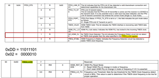
I have issue with multiple boards in a know good design (we have built hundreds that work).  We are not getting link to our display and the output of register 0x5A is 0x02.  On a working board the result is 0xDD.

This bit implies we are not getting a clock in from the HDMI interface, but I did verify we were seeing a clock at the pins of the 929.  Could it mean something else?

Here is the entire register dump from the 929:

No size specified (using byte-data access)
0 1 2 3 4 5 6 7 8 9 a b c d e f 0123456789abcdef
00: 18 00 00 da 80 00 00 c0 c0 00 00 00 00 22 22 02 ?..??..??....""?
10: 22 00 00 e8 00 00 fe 1e 7f 7f 01 00 00 00 01 00 "..?..?????...?.
20: 00 00 25 00 00 00 00 00 01 20 20 e0 00 00 a5 5a ..%.....? ?..?Z
30: 00 00 00 00 00 00 00 00 00 00 00 00 00 00 00 00 ................
40: 14 5c 00 00 80 00 00 00 00 00 00 00 00 00 00 00 ?\..?...........
50: 97 a1 1e 00 0c 0c 00 00 00 00 02 a0 02 06 44 00 ???.??....????D.
60: 22 02 00 00 10 00 00 00 00 00 00 00 00 00 00 00 "?..?...........
70: c2 c4 c6 82 7c 5a 00 c2 c4 c6 82 7c 5a 00 00 00 ????|Z.????|Z...
80: 00 00 00 00 00 00 00 00 00 00 00 00 00 00 00 00 ................
90: 00 00 00 00 00 00 00 00 00 00 00 00 00 00 00 00 ................
a0: 00 00 00 00 00 00 00 00 00 00 00 00 00 00 00 00 ................
b0: 00 00 00 00 00 00 00 00 00 00 00 00 00 00 00 00 ................
c0: 00 00 a8 00 40 00 00 00 c0 00 00 00 00 00 ff 00 ..?.@...?.......
d0: 00 00 00 00 00 00 00 00 00 00 00 00 00 00 00 00 ................
e0: 00 00 a8 00 40 38 00 00 00 00 00 00 00 00 00 00 ..?.@8..........
f0: 5f 55 42 39 32 39 00 00 00 00 00 00 00 00 00 00 _UB929..........

  • Our deserializer is the DS90UB926

  • Hi Michael,

    Do you have the register dump of a known good system?

    I did verify we were seeing a clock at the pins of the 929. 

    Are you saying the CLK input to the 929 at pins 49/50 were captured and they look as expected compare to a known good system? Did you check the freq. of the clk, and does it match a known good system?

    Also, can you clarify the following:

    • Are you getting PCLK out on the 926 side?
    • When the failure mode occurs, does lock stay high?
    • Do the failing system recover with PDB or power cycle , etc?
    • If you have failing system, have you tried ABA swap? Basically replacing the suspect 929 with a known good 929 to see if the issue goes away ?

    As a preliminary review, it seems that your TMDS CLK is not stable for the cases that are reading 0x02 which means that the TMDS clock frequency coming into the 929 is too low for proper operation.

    Regards,
    Fadi A.

  • So to answer your questions:

    Replacing the part with a part that worked on a previously good board did fix the issue.

    Here is the register dump from a working board:

    root@m500-main-2:~# i2cdump -y 3 0x0c
    No size specified (using byte-data access)
    0 1 2 3 4 5 6 7 8 9 a b c d e f 0123456789abcdef
    00: 18 00 00 da 80 00 58 c0 c0 00 14 56 07 22 22 02 ?..??.X??.?V?""?
    10: 22 00 00 e8 00 00 fe 1e 7f 7f 01 00 00 00 01 00 "..?..?????...?.
    20: 00 00 25 00 00 00 00 00 01 20 20 c8 00 00 a5 5a ..%.....? ?..?Z
    30: 00 00 00 00 00 00 00 00 00 00 00 00 00 00 00 00 ................
    40: 14 55 00 00 80 00 00 00 00 00 00 00 00 00 00 00 ?U..?...........
    50: 97 a1 1e 00 0c 0c 2a 00 00 00 dd a0 02 06 44 4b ???.??*...????DK
    60: 22 02 00 00 10 00 00 00 00 00 00 00 00 00 00 00 "?..?...........
    70: c2 c4 c6 82 7c 5a 00 c2 c4 c6 82 7c 5a 00 00 00 ????|Z.????|Z...
    80: 00 00 00 00 00 00 00 00 00 00 00 00 00 00 00 00 ................
    90: 7e 0b e8 80 eb 00 00 00 00 00 00 00 00 00 00 00 ~????...........
    a0: 00 00 00 00 00 00 00 00 00 00 00 00 00 00 00 00 ................
    b0: 00 00 00 00 00 00 00 00 00 00 00 00 00 00 00 00 ................
    c0: 00 00 a8 00 68 00 00 e0 c0 00 00 00 00 00 ff 00 ..?.h..??.......
    d0: 00 a1 00 30 00 00 00 00 00 00 00 00 00 00 00 00 .?.0............
    e0: 00 00 a8 00 68 38 00 00 00 00 00 00 00 00 00 00 ..?.h8..........
    f0: 5f 55 48 39 32 39 00 00 00 00 00 00 00 00 00 00 _UH929..........

    So it appears this bit does NOT have anything to do with the HDMI clock input to the 929

  • Hi Michael,

    How many failures do you have?

    I could go ahead and review the reg. dump but in the meantime based on your comment below. 

    So it appears this bit does NOT have anything to do with the HDMI clock input to the 929

    If ABA swap follows the IC it might be that those ICs have gotten zapped due to over-current or over-voltage event such as EOS or some other issue might have occurred during power up, it's hard to tell what exactly is happening, so I would suggest having those failing ICs sent to quality for further investigation.

    You would need to send the failing loose ICs through the quality channel for testing to see if those parts have any issues.

    Regards,
    Fadi A.