This thread has been locked.

If you have a related question, please click the "Ask a related question" button in the top right corner. The newly created question will be automatically linked to this question.

TMS320F28384D-Q1: C2000 microcontrollers forum Ethernet controller (DP83848j). was burned or power failure

Part Number: TMS320F28384D-Q1
Other Parts Discussed in Thread: DP83848J, TMS320F28384D, TMS320F28386S

Dear sir, Good evening, We are using the customized board for ti controller ( f28384dptpq ) with Ethernet controller (DP83848j). The TI controller with Ethernet controller (RJ45 connector part no is 749801021CA) are working fine for access the programming and communicate to PC via Ethernet. After some time (1 or 2 days later) the Ethernet connector (DP83848j) )was burned. this is repeated for 3 to 4 time, every time we replace the new Ethernet Ic and check the board was working fine. we ensure that there is no physical shorted. please find the attached Schematic diagram for your reference. Kindly suggest how to avoid the ic burned.

0334.Schematic_3_TI_Controller copy copy_2022-09-30.pdfregards EG.Rajendhran

  • Raj, 

    I looked at your schematic and didn't see anything glaringly wrong with your DP83848 implementation, however I typically support C2000 products. Let me try to see if I can get someone on the PHY team to look more closely at it. If it comes back that there may be a problem with the C2000 implementation I can help support you!

    Expect a reply in the next day or so.

    Regards,
    Cody   

  • Hi Raj,

    What do you mean "The Ethernet connector was burned"? What is the symptom you are seeing when this happens?

    I will review the Ethernet PHY portion of the schematic and get back to you within 5 business days.

    Thanks,

    David

  • Hi Raj,

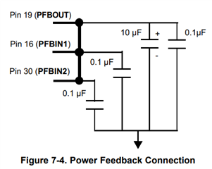
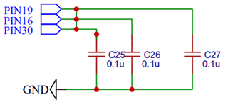
    The power feedback circuit is not correct in your schematic. This may be a cause of your issue. Please add a 10uF tantalum cap to pin 19

    Are the decoupling caps placed very close to the supply pins of the PHY? I also do not see a 10.0-μF capacitor near the PHY for local bulk bypassing between the VDD and ground planes (section 7.4 of datasheet). 

    Please fix these issues and let me know if the problem resolves.

    Thanks,

    David

  • Thanks for the reply...

    Now we placed the 10 uf tatanium capacitor across the  PBOUT to GND.

    All the capacitor are close to the power supply.

    But the problem remains same.

    Actually we have fabricated the 20  nos of board, some of the board was failure.

    While we power on the board normally it consumed 50 mA, but sometimes we power ON it consumed 0.5A then we check the board there is short cirucit in the Ethernet controller IC (DP83848).

    We are using the 24M hz crystal in  f28384dptpq  controller.

    Kindly suggest to resolved this problem.

    Regards

    EG.Rajendhran

  • Hi Raj,

    Is anything different between the 50mA and 500mA power up case?

    How have you checked that there is a short circuit in the PHY? Have you checked for shorts on the board?

    Thanks,

    David

  • Hi David,

    There is no difference in the power up case.

    Initially the board seems to be working fine. But this control failure seems to be unpredictable..

    Some times the controller (DP83848J) fails when we switch on the board.

    After flashing the controller program  to f28384dptpq  via xds100v2  the ethernet controller  got fails or overheat.

    We are identifying the Ethernet failure, when we try to ping the board it is not responding and the established Ethernet connection was lost with the PC.

    At that time we find that the board consumes 0.5 A..

    Kindly suggest further to resolve this issue.

    Thanks,

    Rajendhran.


  • Hi Raj,

    Let me bring this up with the team and get back to you tomorrow.

    Thanks,

    David

  • Hi Raj,

    Can you describe the behavior of the PHY after the burn occurs? Can you read/write registers? Can you see any toggling of the clocks? 

    Please probe the voltage on the supply pins during power up to see if there are spurs above the maximum ratings.

    I am also suspecting the possibility of a physical soldering issue. Please see the following app note for QFN attachment: SNUA271

    Thanks,

    David

  • Hi David,

    good evening,

    Thanks for the reply...

    when we try to ping the board it is not responding and the established Ethernet connection was lost with the PC.

    At that time we find that the board consumes 0.5 A. We observed all time it happen only power up time or we flashed the program it was done perfectly and we try to check the ping its not happened.

    we cannot predictable why it happen during the power up time.

    we have 20 nos board, some of the board we observed.

    we have one Gpio line is used for LED it will glow continuously in controller ( f28384dptpq), but ethernet controller is not pining at the time, we observed the power consumption is high so that we we did not check the read/write registers.

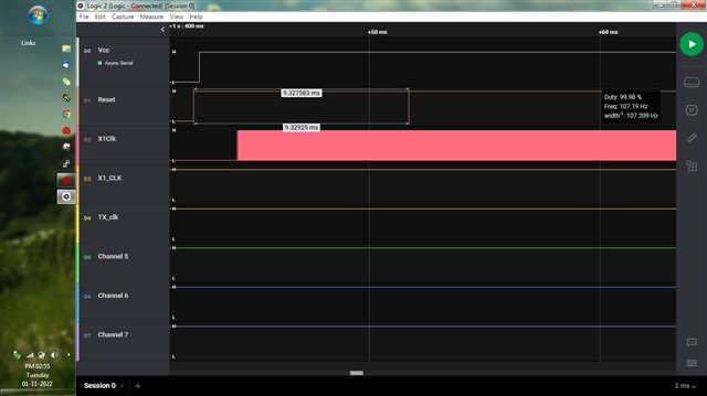
    We  checked the cystral X1 we getting the 25Mhz clock is fine and also check the TX Clock is 25MHz  image for your reference. 

    we are using the converter TSR1-2433 power supply for ethernet controller, there is no drops and flucutation.

    Soldering we are given outsource they are also using the pick and place machine (in automation).

    Our project is  20 nos of board used at the time in Ethernet controller switch to access the function.

    Our suggestion.

    IS there is any abnormal in External reference clock X1  crystal? or can we use the oscillator. 

    is there is any problem in impedance line in our design?

    we need to change any other power supply to controller DP83848J instead of TSR1-2433?

    Is there is any additional capacitor value we have to added in power line?

    Kindly give the suggestion for further...

    waiting for your valuable revert.

    Regards

    EG.Rajendhran

  • Hi Raj,

    I am suspecting some absolute maximum ratings are being exceeded here. Please provide a scope shot of the supply pins, CLKOUT, and reset pin during power up. 

    Please send a 1 screenshot of a good board, and 1 screenshot after the failure. 

    Thanks,

    David

  • Dear David,

    Thanks for the reply...

    Please find the screenshot  for working board

    (Pin no.28) New folder (3).rarX1_clock level voltage is 1.34 to 1.8V.

    Reaming VCC and Reset line voltage is 3.3v Dc.

    We capture this is logic analysis.

    after the failure:

    We cannot capture because the power line 3.3v and ground are shorted and the IC got overheat so may be it affect the Controller f28384dptpq. so that we cannot capture the after failure board.

    Regards

    EG.Rajendhran

  • Hi Raj,

    I cannot see the voltage levels in the image you have sent. Can you send an oscilloscope capture? Would like to know the value of Vcc, and see if any overshoot at power up.

    Is the PHY becoming very hot prior to failing? To test if this is a thermal failure, can you perform a temperature test at 70C ambient and see if the failure occurs any sooner than normal. 

    Thanks,

    David

  • hI,

    Good day,

    Thanks for the previous support.

    Previously we using the  ethernet controller (DP83848J) with Rj45 (7498010210A) and  TI controller (TMS320F28384D).

    Now we changed the Ethernet controller (LAN8710A) with Rj45 (7498010210A) and  TI controller (TMS320F28386S).

    Please find the schematic for your reference. now we are trying to connect Ethernet (RJ45 connector) to PC its not detecting the network and sharing page.

    Programming code and pin mux are same for previous used.

    we checked the clock in scope its fine.

    1) Can u suggest how to find the Ethernet controller  or Ti Controller  which is not working.

    2) Is this TI controller (TMS320F28386S) is suitable for this Ethernet controller (LAN8710A) and Rj45 (7498010210A).

    Waiting for your valuable revert.

    Regards

    EG.RajendhranTI_BMS_1V3_schematic.pdf

  • Hi Raj,

    I cannot be of further assistance if you are no longer using a TI PHY. The TMS320F28386S supports MII and RMII so will work fine with the Microchip PHY using either of those interfaces. 

    Thanks,

    David