This thread has been locked.

If you have a related question, please click the "Ask a related question" button in the top right corner. The newly created question will be automatically linked to this question.

TUSB212: Questions of TUSB212

Part Number: TUSB212

Dear Team,

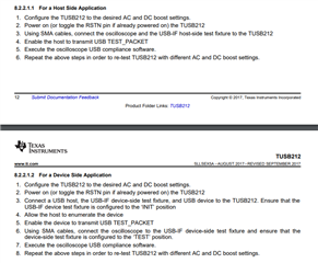
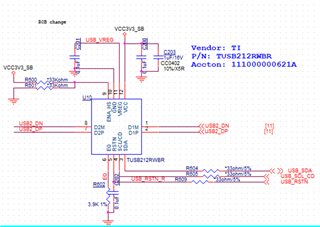
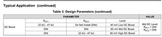
I found that I adjusted the resistance of pin9, but the USB signal did not change. The following is the circuit connection, please review and analyze the reason? What else can be adjusted to change the waveform.

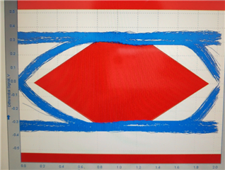
 eye diagram of pin9 floating 

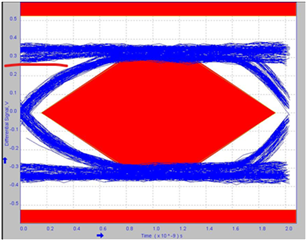
 eye diagram of pin9 pull up 33K

Many Thanks,

Jimmy

  • Hi Jimmy,

    Is R601 being removed from the schematic to allow for the ENA_HS pin to pull up via R600? I just want to double check.

    Next, please make sure that the TUSB212 is turning on by checking the ENA_HS pin and the CD pin after reset. If turned on, both these pins should have a high output.

    If the TUSB212 is not turned on, please make sure to follow the test procedure instructions found in section 8.2.2.1 of the TUSB212 datasheet.

    Thanks,

    Ryan

  • Hi Kitto,

    1. The current R600 is welding 33K, R601 deleted
    2. The mentioned ENA_HS pin and CD pin should both be PIN9, right?
    3. If turned on, both these pins should have a high output.--------You mean, if the ENA_HS and CD pins are turned on correctly, the output will be high? If it is, my question is that the R600 is welded to pull up, and the default state of this pin should be high.
    4. The PINs of D1P/M and D2P/M are correspondingly connected together. Is there any requirement for the signal flow, must it be D1P/M to D2P/M? or both?

    Many Thanks,

    Jimmy

  • Hi Jimmy,

    1. Got it.

    2. Pin 9 is ENA_HS, Pin 4 is the CD Pin.

    3. Yes, if the device detects a connected USB and can see high-speed signals, the output of both these pins should be high. 

    4. The redriver uses pin 9 at reset to sense what voltage is going into the pin to determine what level of DC_Boost is needed. After the device comes out of reset, pin 9 turns into an output pin, outputting the signal of ENA_HS.

    5. D1P should connect to D2P, and D1M should connect to D2M.

    If you want, you can send a schematic to me on this thread or through a PM, and I can give it a look for you.

    Please let me know if you have any other questions or need clarification!

    Thanks,

    Ryan