This thread has been locked.

If you have a related question, please click the "Ask a related question" button in the top right corner. The newly created question will be automatically linked to this question.

TCAN1042V-Q1: Sizing of filter capacitor

Part Number: TCAN1042V-Q1

Hi, 

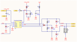
Please find below schematic. We are seeing CAN IC failure on field with no filter capacitor (C6, C7, C8). Please suggest how to size them for better reliability. We are operating at 500kbps, and data send frequency of 500ms. There are 4 nodes in the CAN network. Our node is a stub node with below specs. 2 other nodes have 120 ohm each, 1 other stub node has 1kohm termination resistor.

Typical failure cases are: VCC-GND Short. Few other cases, we are working, will update soon. C24 is 10mm far from IC.

  • Hi Shyama, 

    Bus filtering capacitors act primarily to improve signal quality by reducing high frequency ringing on the analog signal lines. Their secondary function is to provide minimal overvoltage protection by slowing transient edges. However, the majority of survivability will be determined by the CAN IC itself and any additional external protection such as TVS diodes. 

    Can you please elaborate more on the device failures and the conditions that caused them? What IC pins appear to be damaged (impedance measurements of the pin to GND vs a known good device is a good way to check this). Is the IC still partially functional after failure (both CANH and CANL drivers, differential receiver) or is the device completely unresponsive? Does the TVS diode show any signs of damage? What conditions were present before the failure was detected - any ESD testing? Technician handing? Harsh electrical environments?

    Let me know if you have any questions in the meantime.

    Regards,
    Eric Schott