This thread has been locked.

If you have a related question, please click the "Ask a related question" button in the top right corner. The newly created question will be automatically linked to this question.

DS90UB936-Q1: mismatch between GPIO pins status and 0x0E registers

Part Number: DS90UB936-Q1

Hi Expert,

My customer found mismatch between GPIO pins status and  0x0E registers with some samples

They set GPIO pins as below,

GPIO1=High or Low,   GPIO0=low, GPIO2 to 3=low, GPIO4 to 5 = NC

Normaly,  they can read the value 00 at GPIO1=low in 0x0E register,  Also, they can read the value 02 at GPIO1=high in 0x0E register.

However customer found some smaples that show abnormal value, like 10, 12 or 22.

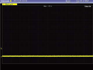
GPIO4 and GPIO5 voltage have shown "low" in waveform. the address of 0x0F,0x10~16,0xBE was shown default setting GPIO4-5.

Could you please give me your comment for reason of this issue?

Have we done about GPIO screening test in production test?


Thanks

Mukuno

  • Hey Mukuno,

    How is the customer setting up GPIO0-3 if you are indicating that 0x0F,0x10~16,0xBE are default? Can we just get a register dump of the GPIO to see what they are being configured?

    Also, can you show us the waveforms on GPIO 4 and 5? How many samples did the customer identify? 

    Glenn 

  • Hi Glenn-san

    Register value,

    Address Value

    0F        02

    10        41

    11        00

    12        00

    13        00

    14        00

    15        00

    16        00

    BE        00

     the waveforms on GPIO 4 and 5

      > How many samples did the customer identify?

    46pcs

    Thanks

    Muk

  • Mukuno-san,

    Let me look into this. 

    Glenn 

  • Muk,

    Register 0x0E only reports the status of the GPIOs if they are configured as inputs. In your config based on 0x0F, only GPIO1 is configured as an input and all the other GPIO are configured as outputs. SO you should not use 0x0E to reliably read back the status of GPIO0 or GPIO2-6

    Best Regards,

    Casey 

  • Casey-san

    Thank you for your answer.

    Is it meaning, If customer set "output" by mistake, then they will try to read 0x0E value, those data will be indefinited (1 or 0)?

    If they set INPUT disable in 0x0F, how will GPIO internal pull down work?

    Is it any probem to set INPUT disable, as termination for unused pin?

    Thanks

    Mukuno

  • Mukuno-san,

    Let me look into this.

    Glenn 

  • Hello Mukuno-san,

    If the GPIO is set to be an output, then register 0x0E will not report the correct status of that GPIO.

    If you want to get the correct status for any GPIO, in reg 0x0E, then you shall set that GPIO to an input in reg 0x0F.

    If you enable the GPIO as output, then internal pull down will be disabled automatically. If you keep the GPIO settings to default, the GPIO will be configured to input with internal Pull-down enabled.

  • Jaradat-san,

    Thank you very much for your supporting.

    >(your commnent) If you enable the GPIO as output, then internal pull down will be disabled automatically. If you keep the GPIO settings to default, the GPIO will be configured to input with internal Pull-down enabled.

    Is it meaning, if they set Input disable in 0x0F,  internal pull down will be disabled automaticall? 

    Also, Is it any probem to set INPUT disable, as termination for unused pin?

    Thanks

    Mukuno

  • Hello Mukuno-san,

    It is recommended to keep unused GPIO setting to default, which is input with enabled pull-down. If you disable input, it means you put this GPIO to work as output with no internal pull-down!! Which means a floating GPIO, and I do not think this what you want in your system.