This thread has been locked.

If you have a related question, please click the "Ask a related question" button in the top right corner. The newly created question will be automatically linked to this question.

DS90UB904Q-Q1: Troubleshooting and knowing what resets the PLL

Part Number: DS90UB904Q-Q1

Hi Team,

Our customer encountered a problem with some batch of DS90UB904Q and would like to ask some diagnostic test to determine the causes the device to "reset"/loose PLL lock. Please see the details of his inquiry below.

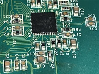
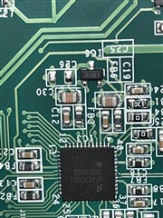
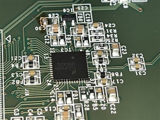
We have an issue with DS90UB904Q PLL not locking. What could the issue be, any reported batch issue or other things as we only have this problem on some batches
Batch starting with 8aa1 works. Batch starting with 97ae does not work
We have confirmed that the board is not the issue by switching between IC batches on the same board.
Good 8aa1 was bought from Digikey. Bad 97ae was bought by our EMS from rochester
Can you suggest things for me to test meanwhile? To find if it's a tolerance issue on the board.
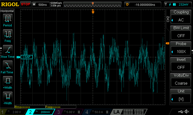
So PLL is not locking on bad boards. The LOCK output is going LOW many times and we loose the picture on the display when it happens.
What causes the chip to "reset"/loose PLL lock?

Regards,

Danilo

  • Hello Danilo,

    Can you please send pictures of one or two devices to marking, from the good batch and from the suspect batch?!

  • We tried to increase the pclk frequency from 10MHz(the frequency used in the product) to 16MHz. Batch 74c3fvug3 went from glitching picture(PLL loosing lock) to good picture.

    Batch 97AE had the PLL lock failing each 10ms with 10MHz. At 16MHz pclk the PLL lock was longer, but still failed each second.

    Could this indicate som other issues on the board or is the PLL fail indicating bad 904s? 

  • The good batch is 8AA187UG3

  • Bad batch 97AE7EUG3

  • Batch 74CJFVUG3 that is glitching at 10MHz but works good at 16MHz

  • It looks right now after testing many boards that 10MHz is not enough for stable PLL lock. 16MHz works much better. What margin has Texas tested with at the lower limit?

  • Hello John,

    We do test with big margin, at least 10%.

    But this issue can be really anything related to your transmission channel, from Cable, connector, PCB, AC-Coupling capacitors, Jitter, Noise ...to power-supply noise.

    What Cable length are you using? Can you test with a shorter or longer cable?

    Will restarting the DES (digital reset reg 0x01[0]) recovers the issue?

    Can you try writing reg 0x04 with the value 0x01 or 0x03 or 0x0F?

    Can you please send your schematic and layout to be reviewed?

    Otherwise, please measure the following parameters and make sure these are d/s compliant on the good boards and the suspect boards:

    - Power-supply noise, as per page 7

    - CML RECEIVER DC SPECIFICATIONS (RIN+, RIN-), page 8/9

    - Receiver Clock Jitter, Deserializer Period Jitter, Deserializer Cycle-to-Cycle Clock Jitter (page 11)

  • We are using 75 cm SATA 3 cables with diff pair on A and 5V on B channel. But we tested with the exact same cable, PCB etc and the only difference was the batch. We tested 10 MHz, 16 MHz and 30MHz, the more Hertz the more batches passes the test.

    I can't see any issue with the powersupply noise, but I don't like how the diffpair looks like. Is there a reference of how a good diff pair signal should look like? This is how our looks, maybe you can see the issue and suggest things to test.

    The design is basically the reference in the datasheet.

  • John,

    The measured signal looks normal. We can't see much on this scope shot since there are forward channel and back channel on top of each other.

    ---------------

    can you please response to the other questions?

    Can you test with a shorter or longer cable?

    Will restarting the DES (digital reset reg 0x01[0]) recovers the issue?

    Can you try writing reg 0x04 with the value 0x01 or 0x03 or 0x0F?

    Can you please send your schematic and layout to be reviewed?

    Otherwise, please measure the following parameters and make sure these are d/s compliant on the good boards and the suspect boards:

    - Power-supply noise, as per page 7

    - CML RECEIVER DC SPECIFICATIONS (RIN+, RIN-), page 8/9

    - Receiver Clock Jitter, Deserializer Period Jitter, Deserializer Cycle-to-Cycle Clock Jitter (page 11)

    At least if you can test the first 3 points would be a good start.

  • Can you test with a shorter or longer cable?

    Will restarting the DES (digital reset reg 0x01[0]) recovers the issue?

    Can you try writing reg 0x04 with the value 0x01 or 0x03 or 0x0F?

    Can you please send your schematic and layout to be reviewed?

    We have tested with many cable lengths and brands, no difference.

    Changing the registers does not help, and it's hard when loosing the connection to the DES all the time due to the PLL clock not locking.

    Sent the schematic in private message.

    Only difference we can see is that a higher PCLK is helping the PLL to lock on bad batches.

  • Hello John,

    I think at this position you need to get help from your local TI representative (I think "Danilo Austria") to file a quality issue and send one or two parts for analysis.