This thread has been locked.

If you have a related question, please click the "Ask a related question" button in the top right corner. The newly created question will be automatically linked to this question.

THVD2410: Problem with RS485 driver

Part Number: THVD2410

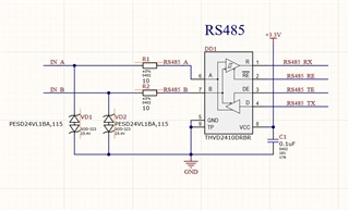
Hello, I have a problam with your RS485 driver: THVD2410DRBR. Below I give part of my circuit. All 4 output pin conected to a outer conectors. There are 4 wires on the line to the sensor: power, ground, A and B. The power line is +24 V. The user can accidentally mix up the wires and connect erroneously to line A or B to +24 V, and connected +24 V line to line A or B . The datasheet says that the driver can withstand the voltage on lines A and B up to 25 V (typically), and up to a maximum of 70 V (as I understand it, this is to protect against switching currents). During our tests of such an incorrect connections, there are times when the driver had broken. I would like to clarify why this is happening? Maybe I did not understand something in the documentation or interpreted it incorrectly?

  • Hi Igor,

    A few questions just to help me clarify the issue:

    1. Both the device and power source share the same ground connection correct?

    1a) If yes - is the a large distance between connection points - and is there large ground currents in the system as ground potential differences can result in the device "reading"  a voltage that wasn't intended for.

    1b) If no is the difference in the ground points known?

    2. Is the driver enabled upon connection of A/B to 24V - i.e. is the driver actively driving during failed cases? Or is it in receive mode? 

    3. If the driver is active upon connection:

    3a) How long does the fault condition last

    3b) Do you have voltage measurement across the 10 Ohm resistors during the fault condition

    3c) What is the ambient temperature of the test environment. 

    4. Finally what is considered a "Failing Device" how are you determining that a device has failed. If it won't work again upon repowering -what is failing on the device?

    Essentially - I don't see anything wrong with the schematic. The device is protected up to +/-70V faults and has a common mode range of +/-25V so the voltage itself shouldn't be causing a failure. The potential issue I see is that the junction may be getting damage due to overheating. This device does have a thermal junction feature but the thermal junction feature may not shut off the device at the max rated junction temperature (150C) and is typically shutting it down at 170C. The fold back current feature (reducing short circuit current to +/-5mA compared to up to +/-250mA) doesn't kick in until +/-25V - so at +24V you could see up to +/-250mA current - but if you have some measurements based on the questions above it will help me determine if my initial hypothesis is possible or if it is something else. Also how many units have been failing? 

    Please let me know!

    Best,

    Parker Dodson

  • Thanks for the quick response!
    1. Yes. The distance  between connection points 1 m.
    2. Voltage on the line RE and TE equal zero, but driver is not powered
    3. a. Fault condition set during from several seconds to 60 sec depending on test drivers.
    3. b. Start moment when a I connected you may see on figure below:

    Ignore the purple color.
    3. c. Ambient temperature 23 deg. C.
    4. "Failing Device" I mean situation when driver is not work, and have smаll resistance ( several Ohm depending on failing drivers) between input line A and ground. And the resistor burns too.

    When I connected line sometimes the voltage may bigger then 25 V and may achieve 35 V.
    We tested 5 units and they all failing after that situation. But if I change resistors from 10 Ohm to 33 Ohm all work is good. But work distance of line is smaller.

  • Hi Igor,

    So just to make sure I am understanding  - is the 24V applied directly to A / B pin or is applied to IN_A / IN_B? 

    I think based on the fact that increasing the series resistance helped prevent the issue its applied to IN_A / IN-B - but the colors are a bit confusing as it looks like Blue is input point? 

    So based on the soak time of the fault - I do think it may be related to overheating due to "a short circuit" current event increasing the resistance would decrease the peak current and decrease power dissipation which could mitigate the overheating of the junction. Assuming Input is at IN_A / IN_B - if not there isn't a lot that can be done as the increased junction heating could cause issues. Please let me know so I can verify that.

    There are a couple options  moving forward:

    1. Increase series resistance - as you have seen will reduce peak power dissipation of the device and can prevent damage. The voltage itself isn't the problem - but the resulting effects of the voltage and length of fault is. You are correct in that the trade off of this solution is that maximum bus length can be reduced.

    2. Reduce the clamping voltage of the diodes - it doesn't seem like these diodes will clamp in this event - if the clamping point is set lower the input voltage could be clamped to a lower level reducing max power at IC junction. There are a few trade offs with this solution - it will reduce the operational common mode range - so if in end system a large ground potential difference is present it could cause data to clamp earlier than expected. Another trade off is that depending on clamping voltage much more current may need to be shunted through the device requiring more a more robust protection diode. 

    Please confirm if real system the concern for 24V to IN_A or IN_B or if it is RS485_A / RS485_B (direct pin connection).

    Best,

    Parker Dodson

  • I applied 24V to IN_A / IN_B (inputs pin for circuit).
     Color is confusing, I think about it too, but blue is output. If you look further into the graph, you can see that the blue line has less voltage (due to the drop on the resistor) than the yellow one, which indicates correctness color. You can estimate the current by the voltage drop on the resistor.
    I measured the temperature on the driver at the time of incorrect switching. It does not heat up, but the resistor gets very hot and fails.
    Incomprehensible situation, the driver in this situation should work, but it fails. 

  • Hi Igor,

    That is strange - but based on everything that you have shared - I do think there could be too high a power dissipation just based on the larger resistance helping. I am confused why the device isn't heating up - unless its just too short lived to capture -as it does seem like ~500mA of current (5V / 10 - I think is what I am reading off the graph) is being injected which could very much cause a junction failure due to power dissipation - I am assuming that current injection event is too short lived to cause lasting heating - but the instantaneous  power may be too large in this case which is causing the failure. So I do think your options as I listed up above - it seems to be somewhat of an edge case - but I am assuming the injected current is just too much for the device to handle (RS-485 is limited to 250mA under short conditions - I think I am reading a 500mA injected current about at peak - which I think is the issue - a large series resistance can help overcome this issue with the trade-offs mentioned as above.

    Please let me know if you have any other questions!

    Best,

    Parker Dodson

  • Ok, Perhaps. I don’t understand how current can flow, I don’t  powed the driver, why the input in the driver is open?.

  • Hi Igor,

    A/B pins are going to have an input impedance regardless of VCC level - this device is rated as a 1/8th unit load - which usually can be assumed to be ~96K Ohms between -7V and 12V but this will decrease when moving into the extended common mode range and above could be non-linear (whereas in common mode range the device is pretty linear w.r.t. its input impedance versus input impedance.. The large current surge is mainly due to bus and device capacitance (in-rush current) - I understand where the confusion was - as the driver is limited on current - but when the driver is disabled I believe that spec doesn't apply - so I apologize for that. 

    I'd imagine the inrush is what is causing the issue - and a bulkier resistor or lower clamping diodes would probably be the best bet for solving the issue.

    Please let me know if you have any other questions!

    Best,

    Parker Dodson