This thread has been locked.

If you have a related question, please click the "Ask a related question" button in the top right corner. The newly created question will be automatically linked to this question.

DS90UH941AS-Q1: The REM_INTB waveforms of single output and dual output are different

Part Number: DS90UH941AS-Q1

Hi team,

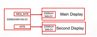
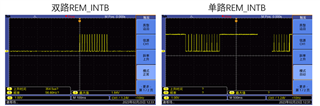
1. When the customer reconfigures the 941 code, he finds that the REM_INTB waveforms of single output and dual output are different. May I ask whether it is normal?

The customer thinks that the waveform inversion seems to appear after configuring the 0x30 register. The dual-channel configuration is 0x01, and the single-channel configuration is 0.

2、And the customer found that the VSYNC and HSYNC of the TFT are also inverting in the case of single-channel and dual-channel output.

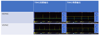
Will there be this difference between single output and dual output?

Thanks!

  • Hi Alan,

    1.) These seem like the correct waveforms according to our info and this app note: https://www.ti.com/lit/an/snla308a/snla308a.pdf .

    2.) Where are these waveforms being taken from? Are HSYNC and VSYNC being probed from the TFT directly? Also, please make sure to double check the measuring methodology, the negative voltage readings are odd.

    Thanks,

    Ryan

  • Hi Ryan,

    Thank you very much for your support!

    The test points of HSYNC and VSYNC are on the screen TFT.

    Attached is the schematic diagram of 948 and test points and VS and HS test waveforms under single and dual outputs respectively.

    1.7z

  • Hi Alan,

    Thanks, I appreciate it. The schematic seems fine, so I would say just make sure no settings on the scope are incorrectly set, as you should not be seeing any negative voltages.

    Thanks,

    Ryan

  • Hi Ryan,

    The waveform problem of Hsync and Vsync, the customer has located the problem, thank you for your support!

    But the customer reported that there is still a problem in this project: when 941 is configured as Splitter Mode, Tianma’s screen cannot be lit, but LG’s screen can be lit; when configured as Single FPD-Link III Transmitter mode (Port 1 disabled) Tianma ‘s screen can be turned on steadily. Can BU give some troubleshooting methods?

    Do different modes have different configuration requirements for the screen? Or are there other checkpoints?

  • Hi Alan,

    When using different modes, such as splitter mode, there are certain requirements that have to be met for successful operation.

    Section 8.4.4, section 8.4.5, and section 8.4.6.4 of the DS90UH941 datasheet detail some of the requirements needed for splitter mode.

    What are the properties of the screens? Are they the same dimensions and PCLK?

    Thanks,

    Ryan

  • Hi Ryan,

    Both screens are 12.3 inches, with a resolution of 1920x720. The following figure is the specification description of the LG and Tianma screens. The CLK is somewhat different. The LG is 89.6MHZ, and the Tianma is 87.7MHZ. The code configuration is set according to the typical value. ,see attached.

    In addition, during the test, the customer directly lowered the PDB of 941 to use the default register configuration (the screen parameters have normal configuration), the LG screen can be lit but the image is abnormal, and the Tianma screen cannot be lit. Does it mean that the problem is not with TI941?

  • Hi Alan,

    Could you possible illustrate how the video is being input into the 941AS?

    It is recommended that both screens have the same resolution and properties, so having differing PCLKs could cause an issue.

    When you say the customer directly lowered the PDB of the 941, do you mean they just used PDB to reset the device to its initial configuration? I imagine the would revert it to initial configuration set by MODE_SEL pins, so unless you are making config changes after the device starts, it should be the same.

    Thanks,

    Ryan