This thread has been locked.

If you have a related question, please click the "Ask a related question" button in the top right corner. The newly created question will be automatically linked to this question.

DS90UB913Q-Q1: Compatibility with DS90UB936-Q1

Part Number: DS90UB913Q-Q1
Other Parts Discussed in Thread: DS90UB936-Q1, DS90UB954-Q1EVM, DS90UB914A-CXEVM, ALP

Hi,

We are currently using the combination DS90UB913Q and DS90UB914Q to transmit video data from an image sensor over a STP cable.
Video format is RAW10 with a PCLK of 33MHz.

Since MIPI is actually required at the output of the deserializer, we would like to switch to the DS90UB936-Q1 component.
This would save us another building block for converting DVP to MIPI.

We built first prototype boards with the DS90UB936-Q1 instead of the DS90UB914Q.
The output data of the sensor were not changed and the transmission of the video data over the same transmission path works as desired.

The problem is that the connection is very sensitive to WiFi signals from external devices, similar to what is described in this thread:
DS90UB934-Q1: FPD LInk III WiFi intereference - Interface forum - Interface - TI E2E support forums

This sensitivity is not present in the combination DS90UB913Q and DS90UB914Q.

First question:
Of course, the signal integrity must be guaranteed and appropriate shielding and its connection must be properly implemented.
This was apparently the reason for the vulnerability to WiFi signals in the above thread.
Are there any other reasons why a combination of DS90UB936-Q1 and DS90UB913Q should be more susceptible to WiFi signals than operation with the DS90UB914Q with the same output data from the image sensor?
I assume that the frequency space used is the same.

The second question refers to the data sheet of the DS90UB936-Q1. Why is only the DS90UB913A mentioned here as a compatible serializer, although the DS90UB936-Q1 enables STP transmission?
Is there a reason not to use the DS90UB913Q here?

Thank you for your feedback in advance.

  • Hello Vincent, 

    The second question refers to the data sheet of the DS90UB936-Q1. Why is only the DS90UB913A mentioned here as a compatible serializer, although the DS90UB936-Q1 enables STP transmission?
    Is there a reason not to use the DS90UB913Q here?

    we do not have the 913Q as compatible to the 936 in the datasheet because this pair was not validated since the 913Q is not recommended for new designs.

    First question:
    Of course, the signal integrity must be guaranteed and appropriate shielding and its connection must be properly implemented.
    This was apparently the reason for the vulnerability to WiFi signals in the above thread.
    Are there any other reasons why a combination of DS90UB936-Q1 and DS90UB913Q should be more susceptible to WiFi signals than operation with the DS90UB914Q with the same output data from the image sensor?
    I assume that the frequency space used is the same.

    You are right! The frequency used on the forward channel and back channel is the same. The only difference is that the 936 uses an external REFCLK where the 914Q does not need that.

    You may try using a REFCLK with spread-spectrum and see if that helps mitigating the issue you are seeing.

  • Hello Hamzeh,

    thank you for your reply.

    You mean something like an SSXO oscillator should be used at the REFCLK input of the 936 deserializer!?
    Does this affect any part of internal FPD-Link processing other than the back channel?

  • Hello Vincent,

    Yes, you may use an Oscillator such as the following, which we have used in our validation.

    SG-9101CGA 25.0000M-C05SJAAAB from Epson.

    Spread type: Center spread
    Speed percentage: +/- 0.5%
    Modulation frequency: 25.4 KHz
    Modulation profile: Hershey-kiss

    Yes, this will have some impact on the 936 CSI-2 output. So, you may want to check with your SoC vendor and ask if they do support SSC.

  • Hi Hamzeh,

    there is no problem with the CSI-2 output.

    WiFi signals are interfering with the FPD-Link connection.
    It can be seen on the LOCK pin which is pulled low everytime WiFi signals are transmitted by external devices. 

    This effect can be reduced to some extent by optimizing shielding and signal integrity.

    But I wonder why this effect is not so pronounced with the 914Q 913Q combination when using the same transmission line.

    I thought the reason might be the PCLK of 33MHz causing instability. But with 50 MHz PCLK  this effect has the same extend. 

  • Hello Vincent,

    I have discussed this with the team, and we believe the WiFi frequency (2.4GHz) should not be an issue of our devices, since these are running at ways lower frequencies. You probably need to monitor power supply pins and/or other devices on the new board to figure out what is being affected by the WiFi signal.

  • Hi,

    I tried to be independent of our deserializing hardware. Because the 954 is largely compatible with the 936 I ordered the EVM DS90UB954-Q1EVM.
    Also, I took the DS90UB914A-CXEVM board for comparison. I then examined the boards sensitivity to WiFi signals.

    I successively connected the same STP transmission line and camera module to them and applied WiFi interference signals from a defined distance.
    It should be noted that the length of the transmission line is already taxing the capabilities of the Deserializers.

    Nevertheless the DS90UB954-Q1EVM board is significantly more sensitive to these signals indicated by periodic pull-downs ot the LOCK pin.
    Whereas the DS90UB914A-CXEVM does not signalize any losing of LOCK state in this environment.

    Does the 914A/914Q allow for a longer range than the 936/954 when using STP transmission?

    Regards
    Vincent

  • Hello Vincent,

    What is the length of the used cable? If using a shorter cable, will you see the same behavior? 

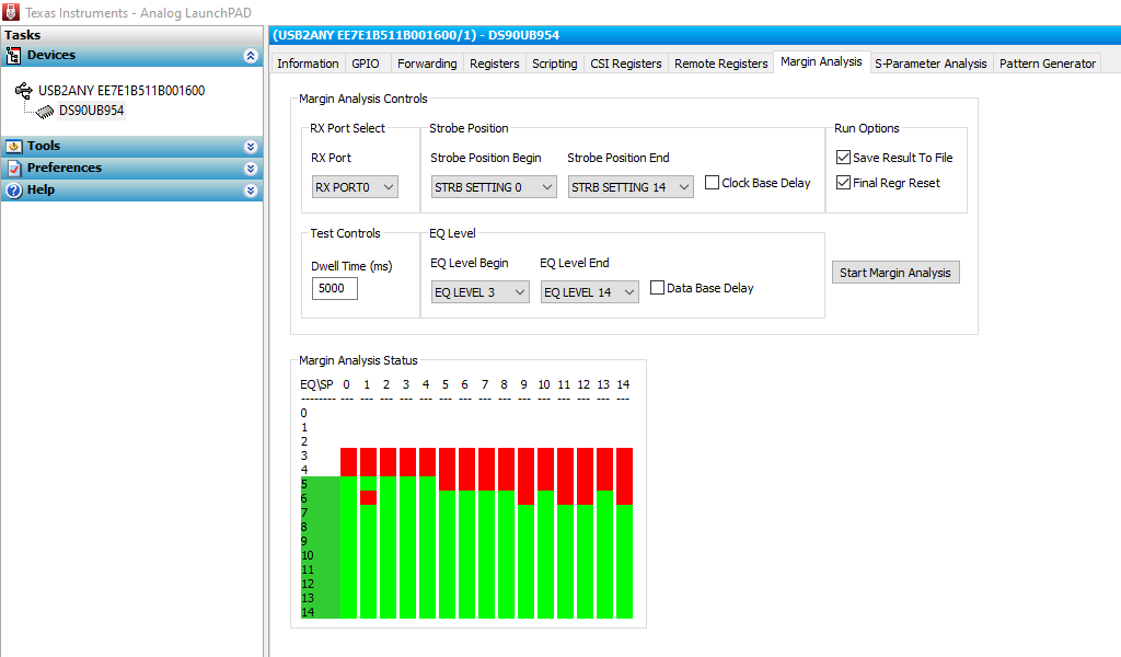
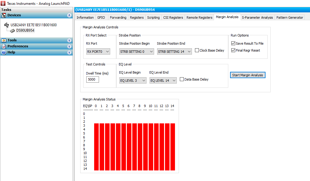
    Can you test the 936/954 using our MAP Tool in the ALP, and provide two screen shots before and during the test?

  • Hi Hamzeh,

    it is a high quality CAT 7 cable with a length of 30m.

    Please see below image for the MAP results when applying no interference signal:


    If you bring a WLAN antenna (12dBm) within 14 cm of the device, the result looks like this:

    Reducing the cable length to 10 m greatly reduces this effect.
    It becomes very hard to unlock the FPD-Link signal by WiFi interferences in any way.

  • Vincent,

    thanks for sharing these details.

    it is a high quality CAT 7 cable with a length of 30m.

    This length of cables we usually do not support. You must have a very good design + the low data rate to be able to support this cable reach. Our typical cable reach is 10 meters for STP and 15 meters for Coax.

    If you bring a WLAN antenna (12dBm) within 14 cm of the device, the result looks like this:

    having such a very strong signal 12dBm at this distance would have an impact for sure. Also, I am not sure if your cable is unshielded!

    Reducing the cable length to 10 m greatly reduces this effect.
    It becomes very hard to unlock the FPD-Link signal by WiFi interferences in any way.

    This is the typical cable reach for STP.

    Also please keep in mind that CAT7 cable is specified for max frequency of 600MHz.

  • Hamzeh,

    I understand your objections.

    But the point I don't understand is, why does  the DS90UB914A-CXEVM board work using the same transmission line and WiFi interference signal without degrading the FPD-Link signal!?


  • Hello Vincent,

    As I said earlier, it could be either a board design issue, where one or more components, such as power components or others, are more sensitive to this frequency band, or the Internal structure of the 936/954 is more sensitive to this frequency band, since these devices have different internal design which runs at higher frequencies.

  • Ok. Thanks for your explanations.